


Revised A
40
6301
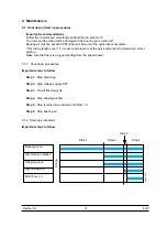
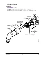
5. Maintenance (continued)
5.3.4 Low voltage cable wiring instructions (continued)
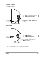
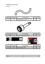
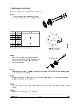
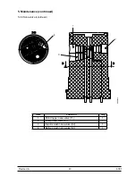
Step 5:
Insert low voltage cable assemblies into the
connector body using the wiring diagram below.
Note: Holes A, E, F, G, & H are not used.
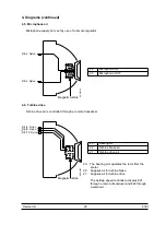
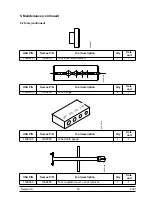
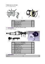
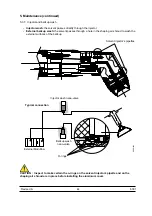
Step 6:
Feed the low voltage cable ends through the
positioning plug washer with its flat side and pin
facing out, then through the PPH 607 quick
disconnect assembly.
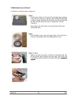
Step 7:
Assemble the two washers and electrical male connector together making sure all parts are correctly
aligned and the mating is flush.
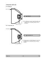
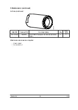
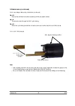
Step 8:
Position the above mentioned assembly into the UHT well by pulling on the cables and using two
fingers to hold the assembly together.
Step 9:
The three o-rings must be in place before tightening connections (please refer to section 5.3.3. for
details).
Step 10:
Tighten the assembly into the robot adaptor.
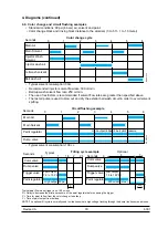
Pin
Wire
Cable
L
Red
1
J
White
K
Black
D
Shield
B
Red
2
C
White
M
Black
DES01482
1
2
D
ES01303
Wiring diagram
A
H
G
F
E
J
L
B
C
K
M
D
DES01298
Alignment Pin


