background image

13

Instruction Manual

부적절 / Incorrect / 

不正确

적절 / Correct / 

正確

공작물 높이가 높다.

Work piece is too tall.

工件高度高。

공작물을 파악하기 위해 높이가 높
은 죠를 사용한다.

Use tall jaws for tall workpieces.

为夹持工件,使用高度高的
卡爪。

공작물 한쪽면이 경사져 있다.
(수직)

The workpiece is off center.

工件的一面有倾斜。 (垂直)

공작물을 파악하기 위해 경사각이 
있는 보조죠를 사용한다.

Use jaws suitable to the work-
piece.

为把握工件,用有倾斜角的
子爪。

공작물 한쪽면이 경사져 있다.
(수평)

The workpiece is off center.

工件的一面有倾斜。 (水平)

공작물을 파악하기 위해 경사각이 
있는 보조죠를 사용한다.

Use jaws suitable to the work-
piece.

为把握工件,用有倾斜角的
子爪。

공작물 파악 깊이가 너무 얕다.

Not enough clamping depth.

工件夹持深度太浅。

공작물을 충분한 깊이로 파악한다.

Use as much depth as possible.

夹持工件深度要充分。

공작물이 한쪽으로 치우쳐 파악
되어 있다.

Unilateral clamping.

夹持的工件向一边倾斜。

공작물을 바이스 중심에 맞추어 
파악한다.

Clamp concentrically

工件要在虎钳的中心夹持。

아래 공간으로인해, 공작물이
부상한다.

Lower part of workpiece is not 
clamped and in result is lifting.

由于下面的空间,工件会浮
起。

공작물의 부상을 방지하기위해,
갈고리 형태의 죠를 사용한다.

Use claw jaws.

为防止工件浮起,可使用钩子
形卡爪。

그림과 같이 가공된 공작물은 모서
리 R값때문에 파악시 틈새가
생기므로, 공작물 가공정밀도에 영
향을 준다.

The R dimension in workpiece 

shown is causing a gap and thus 

insufficient clamping.

如图所示加工的工件,由于边
角R值,在夹持时会出现缝隙,
对工件加工精度有影响。

공작물 모서리 R값으로 인한 틈새
를 만들지 않기위해, 그림과 같이 
보조블록을 사용한다.

Use a shim.

为了避免工件边角R值引起的缝
隙,使用如图所示辅助块。

바이스에 공작물을 파악할 경우 아래의 요령으
로 작업해 주시기 바랍니다.

IMPORTANT

IMPORTANT

重 要

IMPORTANT

유의사항

Work piece

R

工件

공작물

Jaw

Gap

틈새

间隔

Work piece

R

工件

공작물

Jaw

When clamping work, follow the table below.

在虎钳上夹持工件时,请按如下要领操
作。

Summary of Contents for VS

Page 1: ...rstand DANGER WARN ING items in this maunal before operating the vise Please keep this manual by your side for answers to any questions you may have and to check IMPORTANT Standard Machine Vise Instru...

Page 2: ......

Page 3: ...ol which emphasizes important information Warning term DANGER WARNING CAUTION IMPORTANT Indicates an imminently hazardous situation which if not avoided will result in death or serious injury These wa...

Page 4: ...4 Vise 1 7 2 10 2 1 10 2 2 10 3 11 4 12 4 1 12 4 2 12 4 3 MMV 14 5 15 6 16 7 17 8 19...

Page 5: ...ummary 10 2 1 Model coding 10 2 2 Construction and operation 10 3 Mounting 11 4 Precautions 12 4 1 Adjusting stop pin 12 4 2 Workepiece 12 4 3 Using the switch over device MMV 14 5 Maintenance and ins...

Page 6: ...6 Vise 1 7 2 10 2 1 10 2 2 10 3 11 4 12 4 1 Lock pin 12 4 2 12 4 3 MMV 14 5 15 6 16 7 17 8 19...

Page 7: ...orque specifications are used workpiece may be thrown from the chuck Incorrect Correct Danger by discharge of chuck or workpiece in case of damaging of vise Please read this manual before operating th...

Page 8: ...e influence lowers judgment and increases likelihood of accident Loose clothing may be caught in the machine NO Alcohol Drugs NO NO L2 L1 2 L2 L1 2 2 The height of the workpiece should be lower than t...

Page 9: ...ipping workpiece make sure your hand is clear from the gripping area Never attempt to apply excessive force and shock to handle Thoroughly clean the vise The vise may fall and cause injury Vise or wor...

Page 10: ...compresses the disc spring to create force Depending on application you can adjust the vise to use as a general machine vise VS MMV Standard machine vise Mechanical machine quick vise VS 150 Fig 1 VS...

Page 11: ...and sharp edge If the flaw or sharp edge are found repair them with oil stone etc before mounting 3 Carefully position when using T groove 4 Securely fix the vise on the machine tool with body bolt 1...

Page 12: ...otation The stop pin can be adjusted accordingly to jaw width 1 2 CAUTION CAUTION CAUTION Type Widened length 1 2 3 VS 0 100mm 98 200mm 198 300mm MMV 0 115mm 110 230mm 225 350mm 1 2 3 Wodened length F...

Page 13: ...to the work piece Not enough clamping depth Use as much depth as possible Unilateral clamping Clamp concentrically Lower part of workpiece is not clamped and in result is lifting Use claw jaws R The...

Page 14: ...mping on the workpiece the vise will malfunction Reas sembly will be necessary Return the handle until the clutch clicks to completely engage 1 Push the handle 2 Turn the handle 90 in any direction To...

Page 15: ...sliding surface 100mm For 100 mm 100mm 0 015 0 010 2 T The Squareness between guideway of T slot which is bottom of body and Clamping face T 0 015 0 020 3 The parallelism between each clamping face 0...

Page 16: ...MMV Broken force mechanism MMV MMV Replace disc spring or clean and reassemble booster assembly Poor accuracy Incorrect mounting Page 11 Follow the recommended mounting method Page 11 Page 11 Mounting...

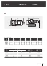
Page 17: ...200 8 57 5 20 5 SB 200T 36 x 20 x 12 VS 250 10 110 0 36 5 SB 250T 36 x 20 x 12 Type A B C a b c d e f g h i j k VS 150 6 150 45 110 470 440 320 288 245 220 180 115 45 283 18 VS 175 7 175 50 132 547 51...

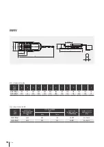
Page 18: ...g key size mm Body Table MMV 150Q 6 4 400 56 0 16 0 VS 175T 34 x 16 x 10 MMV 200Q 8 6 500 94 0 23 0 VS 200T 36 x 20 x 12 Type A B C a b c d e g h i j k MMV 150Q 6 150 51 300 800 620 200 240 133 116 12...

Page 19: ...1 7 Guider 2 8 Stop collar 1 9 Mounting bolt 2 No Name Q ty 10 Key 2 11 Spring pin 1 12 Hex socket head bolt 2 13 Hex socket head bolt 2 14 Hex socket head bolt 2 15 Hex Nut 2 16 Flat washer 2 17 Hex...

Page 20: ...1 No Name Q ty 23 Disc spring washer 6 24 Name plate 1 25 A K A K Pin A K 1 26 Booster spring 2 27 Knob 1 28 Hex socket head bolt 2 29 Key 2 30 Stopper 1 31 Mounting bolt 2 32 Hex Nut 2 33 Washer 2 34...

Page 21: ......

Page 22: ......

Page 23: ......

Page 24: ...st e d P ro d u kt io n u b er w ac h t B au ar t g ep ru ft s ISO 9001 2008 V S M M V VIse VS MMV Instruction Manual VS MMV Samchully Machinery 405 820 99 TEL 82 32 822 4811 FAX 82 32 822 4377 405 82...

Reviews: