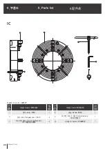
A
B
A
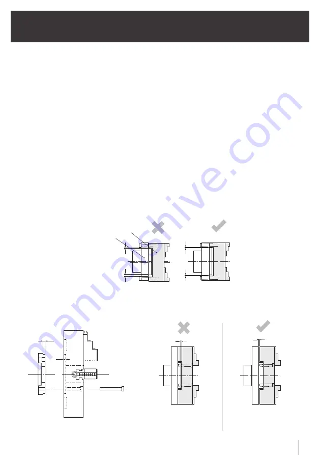
=
>
B
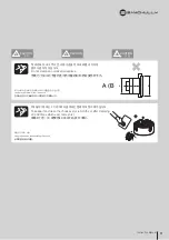
아답터
척
Adaptor
Center of Chuck and Spindle does
not Coincide with each other
Chuck
适配器
卡盘
정도불량의 원인 / Cause poor accuracy /
精度不良的原因
척의 중심과 스핀들의 중심이
일치하지않음
13
Instruction Manual
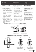
1. Mount the spindle adapter.
Maintain a clearance of 0.02 to
0.03mm between the faces of the
spindle and adapter. Meet the two
surfaces by tightening the bolts.
2. Machine the outer diameter and
face of the adapter.
3. Make the A dimensions 0.5 to 1mm
deeper than F. Double check the
chuck mounting surface and the
center of its outer diameter.
4. After mounting the chuck, check
if jaw movement is smooth. In case
the jaws do not move, make sure
that A is deeper than F by 0.5 to
1 mm.
1. 스핀들에 아답터를 부착합니다.
이때 스핀들의 단면과 아답터의
단면에 틈새(0.02~0.03)를 두고, 볼트
로 고정시 단면에 밀착되도록 합니다.
2. 아답터의 외경 및 단면을 가공합니다.
가공시 단동척 주요치수를 참고하여
가공합니다.
3. A 치수는 척의 단깊이 F 보다
0.5~1mm 깊게 가공하여 부착하
고, 척의 단면 및 외경의 중심을
확인합니다.
4. 척부착후 스크류를 회전하여 죠가
원활히 작동되는가를 확인하고 원활
히 작동치 않을경우 A > F 이 되는지
확인하여 재조립 합니다. A< F 일
경우 죠가 작동하지 않을수도
있습니다.
1. 将适配器装配到主轴上。这时主
轴端面和适配器端面应有间隙
(0.02~0.03),用螺杆固定时使端
面相互密接。
2. 加工适配器外径和端面。
加工时要参考单动卡盘的主要尺
寸。
3. A尺寸加工成比卡盘台深F深
0.5~1mm,装配,确认卡盘端面和
外径中心。
4. 装配卡盘后转动螺丝,看卡爪是
否操作灵活,如果操作不灵活,
查看是否达到A > F,重新装
配。A< F时卡爪有可能不能操
作。
3. Mounting
3. 安装
3. 설 치
아답터의 제작 및 부착
适配器制作与装配
Adaptor manufacturing
and mounting
F
A
Fig.2
Fig.3
아답터 가공이 기준단보다 작은 경우
A < F
A > F
아답터 가공이 기준단보다 큰 경우
The adapter register is shorter than chuck recess
The adapter register is longer than chuck recess
当适配器加工比基准台小时
当适配器加工比基准台大时
작동불량의 원인 / Cause malfunction /
工作不良的原因


