SaMASZ Spin S Operator'S Manual Download Page 29


Operator's Manual 

Round bale wrapper 

Spin S, Spin F


- 27 - 

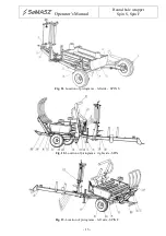
The bales should be wrapped only in positive temperatures. The bales should be wrapped on a 

field or in their storage area.  

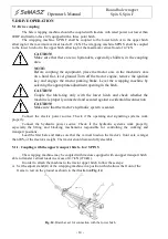
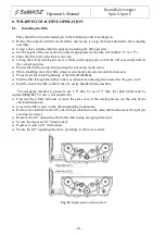
Pay  particular  attention  the  initial  tensioning  of  the  film  (65-80%)

1

.  A  worn  or  unlubricated 

tensioning  mechanism  may  cause  the  film  the  be  wrapped  too  tughtly.  The  film  tensioning  level 
must not exceed 70%.  

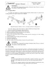
Pull  the  film  at  the  first  bale  as  far  as  possible  from  the  feeder  and  attach  it  using  the  string 

binding  the  bale.  Using  the  control  lever,  turn  on  the  hydraulic  motor  of  the  wrapping  machine. 
While  placed  on  the  rotary  table,  the  bale  is  rotated  by  a  certain  angle  around  its  horizontal  axis 
with every revolution around its vertical axis, which causes the overlapping of consecutive layers of 
film  resulting  in  a  tight  wrap  around  the  bale.  Maintain  the  tractor  engine’s  revolutions  at  1500 
RPM while wrapping. 

Wrap at least 4 layers of film so that each of tchem is overlapped in 50%. 
 
We advise to finish the wrapping after about 24 revolutions of the rotary frame while using 

1' 8"


film or 16 revolutions while using 

2' 5"

 film. Secure the end of the film. A properly wrapped bale 

has four layers of the wrapping film around it. 


Mark  two  vertical  lines  on  the  film  in  a  distance  of  about  4

"

  from  each  other.  The  distance 

between the lines of 7

"

 after tensioning represents 70% of the initial film tension. The width of the 

film measured at the end of the bale may not be lower than 1

' 4"

 when using 

1' 8"

 film and not lwer 

than 

1' 12"

 when using 

2' 5"

 film. 


CAUTION! 
Before  turning  on  the  rotary  frame  drive,  make  sure  that  there  are  no 
bystanders in the working area. 
 
CAUTION! 
Maintaining  the  Rolls  in  good  condition,  especially  their  edges,  minimises 
the risk of the film breaking while wrapping. 
 
WARNING! 
Do not wrap during precipitation. 


If the bale is wrapped too tightly, halt the wrapping process. Establish the cause of excessive 

film tension. Set the proper film tension. Resume the wrapping process. 
 

Use the bales within 12 months from their wrapping date. 
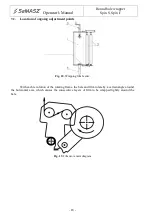
8.5.


Unloading the wrapped bale 


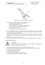
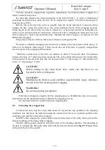
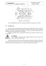
To  unload  the  bale,  stop  the  rotary  table  about  25°  beyond  the  axis  parallel  to  the  wrapping 

machine’s axis and move the table back using the control switch lever to a position parallel to the 
machine’s axis until the rotary table is locked. 

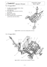
In  SPIN  S  bale  wrapper  the  conical  Rolls  located  on  the  sides  of  the  rotary  frame  prevent  the 

film from falling off the drums while wrapping.  

The film cutting system should be located in front of the wrapping machine. The unloading of 

the bale is completed by lifting the rotary table with the bale as ahown on the Fig. 29. Wrapped bale 
slides down freely to the ground. 


Summary of Contents for Spin S

Page 1: ...awiasta 1 Established 1984 NIP PL 966 159 29 76 tel 48 85 664 70 31 fax 48 85 664 70 41 e mail samasz samasz pl www samasz pl OPERATOR S MANUAL ROUND BALE WRAPPER Spin S Spin F IN129USA001 2014 12 16...

Page 2: ...o mount the machine during operation NOTE Operating bale wrapper without previous familiarizing with its contents as well as by unauthorized personnel particularly by children is strictly forbidden NO...

Page 3: ...OLS AND ONGOING ADJUSTMENTS 17 7 1 Location of the controls 17 7 2 Location of ongoing adjustment points 18 8 WRAPPING MACHINE OPERATION 20 8 1 Installing the film 20 8 2 Hydraulic system 21 8 3 Wrap...

Page 4: ...3 Data plate placement SPIN F Fig 4 Data plate Data plate includes name and adress of the manufacturer model year CE marking means that the produce version number conforms to 2006 42 EC Directive and...

Page 5: ...on of the machine please contact the manufacturer Operator s manual remains an integral part of the machine s equipment Never overload the machine If there are any doubts regarding safety issues pleas...

Page 6: ...actor power hydraulic system MPa 14 Recommended tractor pump output l min 22 Tractor hitch load kN 4 7 1 2 Wheel track in the working setup ft 9 8 Wheel track in the transport setup ft 6 8 Wheel spaci...

Page 7: ...tary frame 11 Hydraulic control unit 5 Loading arm 12 Control levers 6 Drawbar 13 L 02 Counter 7 Support foot The SPIN F wrapping machine consists of the following assemblies Fig 6 Fig 6 Wrapper desig...

Page 8: ...d be conducted on the field or in the storage yard practically immediately after they have been rolled up to 2 hours The wrapped bales should be stacked in up to two layers on a dry level Surface maki...

Page 9: ...e tractor when the tractor engine is running Exercise extreme caution when coupling and uncoupling the wrapping machine with from the tractor The machine should be coupled with the tractor equipped wi...

Page 10: ...rick Follow these guidelines Read and understand the operating manual Do not stand below the raised lifting components of the machine Do not stand in the machine s working area The maintenance and rep...

Page 11: ...ng a locking device as shown on the illustration Fig 9 Lock the bale lowering arm in the top position with the lock as shown on the illustration Fig 8 for SPIN F Disconnect and properly secure the hyd...

Page 12: ...and the emergency lights must be activated inside a built up area turn on the emergency lights and place the warning triangle behind the vehicle unless it is already installed on it make sure that the...

Page 13: ...pinning elements during machine operation 6 Do not approach the working machine Danger of being crushed by a bale 7 Keep a safe distance from the raised arm Danger of being crushed 8 Dangerous zone Be...

Page 14: ...ine tire pressure 17 Avoid contact with liquids under pressure 18 Wear protective gloves Use the required Personal Protective Equipment 19 40x950 warning sign 20 50x300 warning sign 21 40x800 warning...

Page 15: ...Operator s Manual Round bale wrapper Spin S Spin F 13 Fig 11 Location of pictograms left side SPIN S Fig 12 Location of pictograms right side SPIN Fig 13 Location of pictograms left side SPIN F...

Page 16: ...h the lower hitch and check whether the machine is properly connected and secured against accidental disconnection CAUTION Make sure that the tractor s hydraulic system is sealed Connect the electric...

Page 17: ...ction Connect the hydraulic power source Check if the hydraulic systems work properly especially the lifting and blocking mechanisms responsible for controlling the working and transport positions Mak...

Page 18: ...al will be activated Then the power source voltage will be displayed e g U12 7 which denotes voltage of 12 7V Every other condition indicates that the counter is damaged Then the year of manufacture o...

Page 19: ...ms Symbols listed from left to right o Rotary table movement o raising and lowering of the rotary table o Loading arm movement 7 1 2 Wrapper SPIN F D C B A Fig 17 Spin F control lever and control leve...

Page 20: ...ing adjustment points Fig 18 Wrapping film feeder With each revolution of the rotating frame the bale and film rotate by a certain angle around the horizontal axis which causes the consecutive layers...

Page 21: ...e tractor 2 Chain tightening 3 Lubricating point symbols are located on the machine 4 Intersecting axis gear 5 Hydraulic control unit 6 The revolutions sensor is marked with a symbol located on the ma...

Page 22: ...nternal sticky side towards the bale axis Properly set the initial tightening of the film Punkt 8 4 Pull the film through the rubber rollers as indicated on the diagram located on the gear cover Pull...

Page 23: ...ntrol over the engine and hydraulic cylinders is ensured using the control levers located in the tractor s cabin during operation These levers are connected to the three section control unit using Bow...

Page 24: ...can be fixed using its back surface catch WARNING Protect the meter from water chemical agents direct atmospheric precipitation frost high temperature in excess of 50 C and direct exposure to sunlight...

Page 25: ...button within the scope of 10 to 49 wraps Confirm using the C button The counter is ready to work with its new settings Field selection Change the field number using the F1 button 1 2 3 Change the sto...

Page 26: ...to do the following Place the coupled wrapping machine so that the machine s drawbar is paralel to the tractor s axis Remove the pin securing the side wheel and place it in tractor s cabin Move the t...

Page 27: ...nlock the unloading unit Place the loading arm and unloading arm locks in the specified places WARNING Be careful while changing the position of the side wheel There is a risk of the operator s hand b...

Page 28: ...ary table in the same way Lower the grabbing arm to the bottom when the bale rests on the roatry table WARNING Before operation check Whether the wrapping machine drawbar is properly connected to the...

Page 29: ...on the film in a distance of about 4 from each other The distance between the lines of 7 after tensioning represents 70 of the initial film tension The width of the film measured at the end of the ba...

Page 30: ...Correct discharge sequence in SPIN F lifting of the unloading unit 1 tilting of the rotary table 2 lowering of the unloading unit 3 and lowering of the rotary table 4 Fig 29b 8 5 1 Film cutting If the...

Page 31: ...s extremely sharp Danger of hand injury Side wheels located on the sides of the rotary frame prevent the bale from falling off the drums while wrapping 8 5 2 Bale vertical positioning system optional...

Page 32: ...ng work it is required to Remove the locking pin 8 The bale positionong arm 2 will freely drop without touching the ground Set the direction of the bale positioning as indicated by the arrows on the F...

Page 33: ...the machine on a hard flat level ground Disconnect the hydraulic power source and the electric power supply Support the drawbar using a support stand Disconnect the machine s drawbar from the tracotr...

Page 34: ...ows Place the machine on a level surface Place a leakproof tank below the drain plug Remove the drain plug the filler plug and the overflow plug After the oil is drained close the drain plug Pour fres...

Page 35: ...Ongoing maintenance After the period covered by the warranty authorised service stations perform periodical ispections adjustments and repairs 10 3 Ordering replacement parts Spare parts should be ord...

Page 36: ...aulin or film NOTE Store the wrapping machine in an atmosphere free of aggresive agents e g ammonia chemicals 12 PROBLEMS AND THEIR REMEDIES No Problem Possible cause Remedy 1 Wrapping machine s hydra...

Page 37: ...storage Authorised service stations offer both advice and complete machine disposal services Use proper tools and auxiliary equipment for the disassembly jack lift wheel extractor CAUTION During oil d...

Page 38: ...y the user will result in automatic termination of the warranty 9 The manufacturer shall not be held responsible for any loss damage or destruction of the product resulting from causes other than defe...

Page 39: ...pin F 37 15 2 Record of warranty repairs Repairs performed and parts replaced Date seal and signature of person performing the repair Date seal and signature of person performing the repair Date seal...

Reviews: