SaMASZ KDD 861 Operator'S Manual Download Page 12


Operator’s manual 

Double-sided disc mowers 

with central suspension


- 10 - 

3.2.6.


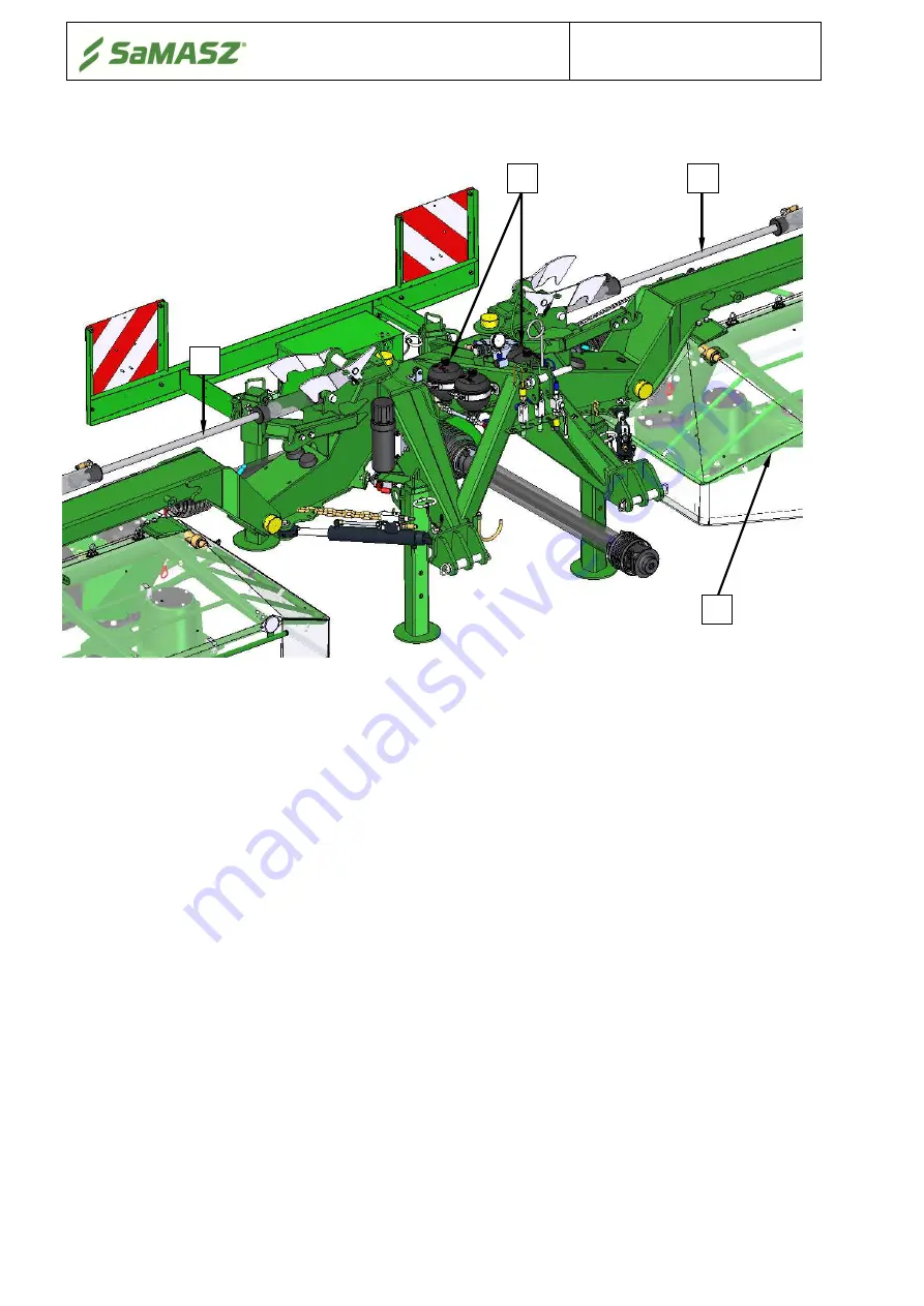
Double-sided disk mowers with hydro-pneumatic support 

All KDD disk mowers are also offered with hydro-pneumatic support (

Fig. 4

). 


Fig. 4.

 Overview of rear disk mower with hydro-pneumatic support 


Hydraulic lifting cylinder (

3

) and hydro-pneumatic suspension driven from the tractor external 

hydraulics and hydraulic accumulators (

1

) are used to adjust the mower to working position.  


3-point  linkage  frame,  onto  which  cutterbar  is  set,  features  hydro-pneumatic  support  (

2

). 

The abovementioned suspension enables the mower’s impact to the ground to be controlled by 
modification of the pressure in hydraulics. 


3.3.


Standard equipment and spare parts 

The mowers are sold with the following standard equipment: 


warranty card, 


operator's manual with catalogue of spare parts 
and declaration of conformity, 


PTO shaft, 


cutting disk with drum (2 pcs.), 


spray paint (150 ml / 5.1 us fl oz),  


reflective plates with lights,, 


frame mounting key, 


cutting disk (2 pcs.), 


disk module (2 sets), 


slide (2 pcs.), 


slide cap (2 pcs.), 


knife base (46 pcs.), 


skew knife L=105mm/ 4.1

''

 (180 pcs.), 


knife holder (2 pcs.), 


inter - skid insert (3pcs.). 


Moreover, mowers with conveyers (KDD S/SL T (H)) are provided with convey belt – 1 pc. 


Summary of Contents for KDD 861

Page 1: ...TOR S MANUAL DOUBLE SIDED DISC MOWER WITH CENTRAL SUSPENSION KDD 861 H 8 60 m 28 3 KDD 911 H 9 10 m 29 10 KDD 912 H 9 10 m 29 10 KDD 941 H 9 40 m 30 10 KDD 861 S SL W H 8 60 m 28 3 KDD 941 S SL W H 9 40 m 30 10 KDD 861 S SL W T H 8 60 m 28 3 KDD 941 S SL W T H 9 40 m 30 10 IN272USA008 2019 04 09 EDITION No 8 Translation of the original operator s manual English Serial number ...

Page 2: ...OWING DISCS HAVE COME TO COMPLETE STANDSTILL DO NOT OPERATE WHEN ANY PERSON REMAINS IN THE DANGER AREA OF 50 m 170 NOTICE Keep this manual for future use Well proven design with thousands of machines in regular use in many countries and quality materials ensure high durability and reliability of SaMASZ mowers We congratulate you on the purchase of your new SaMASZ mower and wish you much pleasure a...

Page 3: ...ng injury abrasion and damage of skin 19 4 9 3 Danger of injury from liquid ejection out of hydraulic system 19 4 9 4 Forbidden actions 19 4 9 5 Residual risk assessment 19 4 10 Safety labels and their meaning 20 4 11 Design and operation of safety breakaway device 25 5 OPERATION 25 5 1 Attaching the mower to the tractor 26 5 1 1 Connecting hydraulic hoses 26 5 1 1 1 Double sided disk mowers witho...

Page 4: ...g swath conditioner 50 6 6 1 Adjusting space between tine conditioner s mask and its shaft 50 6 6 2 Adjusting conditioner s shaft rpm 51 6 7 Replacing conditioner s tines 51 6 8 Adjusting force of the pressure of roller conditioner 53 6 9 Maintenance and service 53 6 9 1 Checking the tension of belt on belt gear for conditioner rollers 53 6 9 2 Daily maintenance 53 6 9 3 After season maintenance a...

Page 5: ...one operates this mower It should be kept near the mower for future use If the mower is used by another operator it should be in working condition and include this operator s manual and all other basic equipment Operator s manual is attached to every machine in order that the operator can familiarize himself with design working principles service and adjustment of the mower The operator should be ...

Page 6: ...mowing should be done a little higher at 2 8 3 1 from the ground The rear mounted disc mower with tine roller conditioner is intended to mow green fodder such as grass and alfalfa on permanent grassland pastures on crop fields without rocks and to form loose rows of cut forage As a result of the passing of the layers of the green fodder through the flails or rollers the grass stems are broken and ...

Page 7: ...pm Emitted noise4 up to 115 dB Tab 2b Specification of the mower Model KDD 861 S SL H KDD 941 S SL H KDD 861 W H KDD 941 W H Working width1 8 60 m 28 3 8 60 m 28 3 8 60 m 28 3 8 60 m 28 3 Number of knives pcs 14 28 16 32 14 28 16 32 Tractor PTO rpm 1000 rpm Tractor power required 147 kW 200 HP 161 kW 220 HP 147 kW 200 HP 161 kW 220 HP 3 point linkage category III Working capacity2 10 0 ha h 11 0 h...

Page 8: ... 0 m Swath width about 2x1 9 2 3m 2x6 3 7 7 about 2x 2 3 2 7m 2x7 7 8 10 about 2x1 4 2 0m 2x4 7 6 7 about 2x 1 8 2 3m 2x 5 11 7 7 Weight3 3920 3500 kg 8642 7716 lbs 4250 3780 kg 9369 8333 lbs 4160 kg 9171 lbs 4450 kg 9811 lbs PTO shaft with overrunning clutch 1100 Nm Cutting speed of the knife 88 m s Disc rpm 3167 rpm Emitted noise4 up to 115 dB S SL mower with swath conditioner with light weight ...

Page 9: ...d 3 2 2 Double sided disc mowers with tine conditioner Fig 3b Parts of SaMASZ double sided mower with tine conditioner KDD S SL 3 point linkage frame 1 enables attachment of the mower to tractor s 3 point linkage Drive from tractor s rpm is transmitted through PTO shaft 9 an intersecting axis gear I 3 onto drive shafts 6 which through intersecting axis gears II 7 power the cutterbars 4 On cutterba...

Page 10: ...e tractor rpm through intersecting axis gear 3 PTO shafts 6 intersecting axis gears 7 and belt transmission 13A or chain transmission 13B is transmitted onto swath rollers 14 Hydraulic lifting cylinders 2 fed from the tractor external hydraulics are used for adjusting the mower to working position Main frame 11 on which cutterbars 4 are installed is unloaded with springs 8 On main frame safety gua...

Page 11: ...le provided in the tractor operator s cabin 3 2 5 Double sided disk mowers with swath rollers and conveyors Fig 3e Parts of SaMASZ double sided mower with swath rollers and conveyors KDD WT 3 point linkage frame 1 enables attachment of the mower to tractor s 3 point linkage Drive from tractor rpm is transmitted through PTO 9 and intersecting axis gear 3 onto drive shafts 6 which through intersecti...

Page 12: ...dro pneumatic support 2 The abovementioned suspension enables the mower s impact to the ground to be controlled by modification of the pressure in hydraulics 3 3 Standard equipment and spare parts The mowers are sold with the following standard equipment warranty card operator s manual with catalogue of spare parts and declaration of conformity PTO shaft cutting disk with drum 2 pcs spray paint 15...

Page 13: ... Symbol Manufacturer KDD 861 H KDD 911 H KDD 912 H KDD 941 H 100 47 6 67 3 956 CS8N121U2R08R07LAX Bondioli Pavesi KDD 861 S T H KDD 861 SL T H KDD 941 S T H KDD 941 SL T H KDD 861 W T H KDD 941 W T H 100 47 6 67 3 956 CH8N121U2R08R09LAX Bondioli Pavesi NOTICE Lubricate the PTO shaft with high quality multi purpose grease every 50 shaft operating hours Fig 5 If access holes are accessible lubricate...

Page 14: ...signed for use by one single operator When using servicing repairing moving or storing the machine the operator must wear safety footwear safety gloves plus ear protection and dusk mask if necessary During use the machine may give rise to dust especially if the soil is dry You are advised to use a tractor with a cab fitted with filters in the ventilation system Failing this wear a dust mask with f...

Page 15: ... always be equipped with operator protection that is required by laws and regulations Never start the mower when the mower blades are off the ground Before you start the tractor make sure that all drives are turned off and the levers that turn the hydraulics are in neutral position Never leave tractor s engine running without supervision Before you leave the tractor turn off the engine and remove ...

Page 16: ...ch all have influence on vehicle driving and machine operation Operator should be familiarized with this manual and follow its provisions Operator should be familiar with working principles of both the tractor and the machine and be able to recognize and avoid hazards resulting from operation of the aggregate 4 3 Conditions of mounting mower on tractor Prior to the mounting operation be sure that ...

Page 17: ... the road after work check to make sure that the tires and soil working tools are clean to prevent the road surface from becoming dirty Make sure that the machine is not damaged during transport No person and no objects must remain on the mower when driving or transporting When taking turns pay particular attention and consider the machine s weight and dimensions Bear in mind that when transportin...

Page 18: ...s set the machine s center of gravity properly To safely support the machine use ropes of adequate length so that the angle between them is no greater than 120 and the angle between the strand and the vertical is no greater than 60 Lift the machine with the utmost caution and move it slowly No one should be within the range of action of the lifting equipment when any transporting operations are be...

Page 19: ...2 11 890 2 11 890 2 11 890 2 11 890 2 11 960 3 2 870 2 10 800 2 7 960 3 2 860 3 F 470 1 6 470 1 6 470 1 6 470 1 6 490 1 7 490 1 7 540 1 9 490 1 7 565 1 10 540 1 9 460 1 6 4 5 Working parts Before operating the mower check knife s knife mounting s and knife holder s condition Worn or damaged knives knife holders or knife mounting should be immediately replaced with new ones WARNING During replaceme...

Page 20: ...nting on a regular basis Front guard 3 should be fixed so that it holds the safety curtain 1 Fix immediately if damaged and replace if missing Do not operate mower without safety curtains Fig 8 Mounting safety curtain guard on the mower 4 9 Residual risk Despite the fact that SaMASZ the manufacturer of the mower has taken great care in the design and manufacturing of the mower certain risks during...

Page 21: ...cribed in operator s manual never operate the mower when it is not in working order or has damaged safety guards never get your hands and legs close to rotating parts of the mower during repair and maintenance of the mower always comply with descriptions included in operator s manual Always do these activities when the tractor s drive is off never operate the mower under influence of alcohol drugs...

Page 22: ... Also be sure that All warning decals are clean and legible All lost or damaged decals are replaced by ordering new decals from your dealer or supplier All persons using this mower have read the section of this manual explaining the meanings of these labels All spare part used for repair of the mower should have all safety labels provided by the manufacturer N 01 Be extremely careful when PTO shaf...

Page 23: ...power lines N 28 N 40 Signs indicating transport holders N 48 Stay away from mower s inclination area N 49 Never stand near tractor s 3 point linkage while steering tractor s lift N 50 Do not stay in the swinging area of mower s parts N 55 N 77 Tension of conveyor s belt N 60 N 63 N 79 ...

Page 24: ...essure Consult technical manual for service procedures N 167 Do not remain on the machine while driving N 168 Do not touch the machine before the rotating parts have not come to a complete standstill N 201 Permissible transport speed N 204 N 205 Use the required Personal Protective Equipment N 115 Locking conveyors N 150 Regulation of support springs N 213 for KDD S SL ...

Page 25: ... mower without conditioner Fig 9b Warning decals placed on the mower with conditioner N 01 N 02 N 03 N 04 N 06 N 07 N 23 N 48 N 49 N 50 N 117 N 167 N 168 N 204 N 205 N 224 N 28 N 55 N 55 N 201 N 14 N 15 N 63 N 109 N 150 N 162 N 01 N 02 N 03 N 04 N 06 N 07 N 23 N 48 N 49 N 50 N 117 N 167 N 168 N 204 N 205 N 224 N 28 N 55 N 55 N 201 N 14 N 15 N 63 N 109 N 150 N 162 N 96 N 213 ...

Page 26: ...er with hydro pneumatic support Fig 9e Warning decals placed on the mower with swath conveyor NOTICE Any spare part used for repair of the mower should have all warning decals provided by the manufacturer N 108 N 60 N 115 N 79 N 80 N 77 N 01 N 02 N 03 N 04 N 06 N 07 N 23 N 48 N 49 N 50 N 117 N 167 N 168 N 204 N 205 N 224 N 28 N 55 N 55 N 201 N 14 N 15 N 63 N 109 N 150 N 162 ...

Page 27: ... used for tilting to the back and lifting of the cutting unit Fig 10 Hydraulic safety breakaway device Fig 11 Simultaneous holding back of the mower up and backwards when safety breakaway advice is used NOTICE Hydraulic safety breakaway device works only if the valve s pressure is adjusted to the factory setting of 1102 lbs 5 OPERATION WARNING Before beginning to use this machine do the following ...

Page 28: ...x on the mower for models equipped with control Place the connected panel in the tractor After the mower has been attached to tractor check balance and steerability of tractor mower set To do this calculate to formulas given in the appendix or weigh the set and then drive on the scales only with front axis of the tractor the mower must be in transport position lifted upwards If the pressure on the...

Page 29: ...ection of the tractor s external hydraulics Fig 14b It would be best if the section would have a free oil flow The tractor should have three pairs of hydraulic connectors Fig 14a Hydraulic hoses mower with conditioners rollers tractor Make sure that the hydraulic hoses have been inserted properly and that the colours of the hoses match Make sure that there are no leaks in the hydraulic system and ...

Page 30: ...ng of left cutting unit on headlands and hose C yellow also with choke valve is used for lifting of right cutting unit on headlands In such mowers it is enough if the tractor has three pairs of hydraulic outputs one with free oil flow Fig 14c Connecting hydraulic hoses to tractor from mower with conditioners rollers in version without controller 5 1 2 Mounting PTO shaft PTO shaft s end with overru...

Page 31: ... the safety guards in tractor mower and PTO shaft if they are placed correctly and are not damaged Damaged or lost parts must be replaced with genuine ones Make sure the PTO shaft is properly mounted It is forbidden to approach the rotating parts because it may lead to serious injuries or even death All service and repair operations must be done only after the tractor engine has been stopped and i...

Page 32: ... 9 Working position for driving on headlands 10 Lifting to headlands of right cutting unit 11 Disabled button 12 Left conveyor starting 13 Right conveyor starting 14 Transport position 15 Pressure modification in unloading system 16 Right cutterbar locking 17 Left cutterbar locking 18 Function button F2 to cancel emergency mode 19 Function button F1 to cancel emergency mode 20 The menu 21 Menu nav...

Page 33: ...o the cutterbar In order to unlock particular cutterbar push either of buttons 8 or 10 again unlocking cutterbar protection is then signalled by dimming of the red diode 5 2 2 Setting mower in vertical transport position In order to set mower in vertical transport position Fig 17 push button 14 while using the lever to control the tractor s external hydraulics If near the end of lifting phase the ...

Page 34: ...ion screen 4 To exit the service mode turn off the panel and on again with power switch Fig 17a 5 3 Simplified control panel The control system comprises controller controls sensors solenoid valves etc installed on the machine and control panel Fig 18 On the upper wall the panel has ON OFF switch allowing for its switching on off display and 7 buttons During normal operation with two cutterbars no...

Page 35: ...utomatic loading of pressure in loading system of cutterbars to a setpoint is carried out after pressing button 1 for left cutterbar or button 2 for right cutterbar which is indicated by corresponding diode flashing red To set any unloading pressure value press and hold button 1 for left cutterbar or button 2 for right cutterbar which is indicated by corresponding diode turning red NOTICE Function...

Page 36: ...ain the lock will be released and the controller will return to its previous condition possibility of operating two cutterbars When left cutterbar lock is enabled function 5 function 1 is disabled unloading should be adjusted only when cutterbar is in working position and function 3 Function 5 left cutterbar lock has a priority higher than function 3 and thus it is not possible to select function ...

Page 37: ...ON OFF switch and then hold button 2 The displayed parameter can be changed by pressing button 2 Tab 6 Work parameters Parameter Opis Current PTO rpm at gearbox input 90 rpm Current PTO rpm of left cutterbar 90 rpm Current PTO rpm of right cutterbar 90 rpm Current pressure in unloading system of left cutterbar 120 bar Current pressure in unloading system of right cutterbar 120 bar Changeable worki...

Page 38: ...after a metal part is approached NOTICE Pressure sensor testing is possible only when filling hydraulic accumulators The displayed active value should be compared to pressure gauge indication To exit controls testing function turn off the control panel with ON OFF switch 5 4 Preparing the mower for transport version without controller To prepare the mower for transport and to meet safety precautio...

Page 39: ... Transport position with lifted mower Fig 21 SaMASZ double sided mower in its transport position WARNING Once the machine is lifted to transport position check whether mechanical locking pawls are properly locked on pins S Transport lock a b around 12 max 13 2 Before transporting your mower in upward position side safety guard must be lifted ...

Page 40: ...ssible values weight axle load towing device load etc according to valid regulations Fig 22 Portable warning light plates 5 6 Moving from transport to operating position WARNING Moving the mower to and from operating position from the transport position should only take place on even and stable ground Prior to making the moves make sure whether there are no unauthorized persons exposed to any haza...

Page 41: ...Mower version with controller Engaging mower s drive should be performed once cutterbar is placed on the ground The following should be performed in workplace and as mower is in operating position hang the machine on the 3 point linkage Connect hydraulic hoses control panel power cord and signal cable RS 232 lower cutterbar so it touches the ground connect PTO shaft extension of the tractor rpm un...

Page 42: ...ngage proper tractor gear and start mowing Even meadows can be mowed at any driving speed however as unevenness occurs the speed should be reduced lift mower on tractor s 3 point linkage up in order to eject cylinder rod to maximum out the cylinder and the cutterbar should touch the ground using tractor s hydraulic valve lever connected with red hose A Fig 14c set the pressure until mower s cutter...

Page 43: ...ar or even its damage 5 8 1 Regulation of cutterbar s pressure on the ground by means of support springs Pressure on the ground is regulated by changing the tension of support springs Decreasing the pressure of the cutterbar on the ground is done by increasing the tension of the support springs from moving the lock in the next hole on the rod towards the springs Fig 24 Increasing the cutterbar s p...

Page 44: ...th 2 drum or 4 drum mowers because the knives work horizontally to the ground and inclined grass bends because of wind blasts After the grass is mowed it stands up which makes an impression of inaccurate mowing Every mower may leave stripes of uncut grass when it comes to the knives which cut the grass towards the grass direction It is a normal phenomenon Practically it is not possible to achieve ...

Page 45: ...a PTO rpm impairs the quality of mowing and in some cases the mower stops mowing too low linear velocity of the knife In contrast with 2 drum mowers straight mounting of the mower and full speed are not always possible Adjust inclination of the mower PTO rpm speed and correctness of knife mounting to get the best results In case of mowing soft meadows the pressure of the cutterbar on the ground sh...

Page 46: ...tionally lifted by tractor s 3 point linkage Fig 26 Fig 26 Mower KDD when taking turns 5 10 Detaching the mower from the tractor WARNING While detaching make sure there is no person in between the mower and the tractor To detach the mower from the tractor do the following Turn off the cutterbar drive tractor s ignition and take the tractor s ignition key out reduce pressure in unloading system lif...

Page 47: ...time e g in winter season the machine should be in an upright position on paved surface Fig 27 with closed cylinders Storing the mower in a horizontal position may cause faster wearing rusting of the cylinder from the inside through vent valve by being penetrated by moisture from the air Fig 27 Double sided disc mower in its storing position 6 MOUNTING AND ADJUSTMENTS 6 1 Assembling disassembling ...

Page 48: ...Damaged or worn elements are dangerous 6 3 Checking the knives and knife mountings All knives should have the same lengths and weights Replace them if necessary only in sets Make sure all knives in a set are of the same length and weight Knife mounting cannot be worn more than provided in Fig 30 If knife mounting is worn too much it should be replaced Fig 30 Permissible wear of knife holder pin on...

Page 49: ... only Long term cutting with insufficient amount of knives will cause permanent damage to the cutterbar not eligible for a repair under the warranty When operating check knives for completeness WARNING When replacing knives the engine must be stopped and the cutterbar must lie on the ground PTO shaft must be disconnected Discs should be perpendicular to cutterbar Fig 31 Quick replacing of the kniv...

Page 50: ...11 H right cutterbar KDD 911 H left cutterbar KDD 912 H right cutterbar KDD 912 H left cutterbar KDD 941 H right cutterbar KDD 941 H left cutterbar KDD 941 H right cutterbar alternate disc rotations optionally KDD 941 H left cutterbar alternate disc rotations optionally Fig 33 Rotating direction of disks in each type of mowers ...

Page 51: ...n screws 3 and locknuts 2 loosen locknuts 4 and screws 5 then adjust shield height and angle 7 tighten screws 5 and locknuts 4 Fig 34 Adjustment of swath guides 1 swath guide 2 locknuts 3 arm adjustment screws 4 locknuts 5 shield adjustment screws 6 guide arm 7 shield In order to set swath width adjustment of swath guides 1 should be performed Fig 35 for KDD S ST SL SLT H loosen eye screw 2 of the...

Page 52: ...guide 2 adjustment screw 6 6 Adjusting swath conditioner 6 6 1 Adjusting space between tine conditioner s mask and its shaft Models KDD S ST SL SLT H Depending on size and thickness of the mowing grass it may be necessary to adjust the conditioner s mask The higher and thicker the grass the bigger the space between the conditioner s mask and its shaft should be A proper setting should be done expe...

Page 53: ...condition of bolts on which flails are set as well as condition of flails themselves When inspecting also take notice of condition of rubbers where flails are mounted applicable to shafts with rubber flail mounts If flails or bolts or rubbers are worn or damaged replace them Bear in mind that flails should be replaced in pairs opposite featuring the same weight in order to keep shaft well balanced...

Page 54: ...tioner light weight swath conditioner Tab 7 Torque values for bolts In the absence of specific torque values the following chart can be used as a guide to the maximum safe torque for a particular size and grade of fastener There is no torque difference for fine or coarse threads Torque values are based on clean dry threads Reduce value by 10 if threads are oiled before assembly 1 Conditioner s sha...

Page 55: ...ioner rollers Power from transmission shafts is transferred with V belts and toothed belts onto rollers axle Constant chain tension is provided by tensioner adjusted with tensioning screw N Fig 41 Properly tensioned V belt once pressed with a finger on tensioner arm K should deflect by about 5 mm Tensioning of toothed belts is factory set and should be enough Fig 41 Adjusting tensioning of belt on...

Page 56: ...the machine operation its technical condition should be examined and special attention should be paid to the hydraulics and the drive Paintwork should be complemented hydraulic hoses checked and lubricated Additionally touch up any chips in the paint check the oil level in the angle drives and the cutterbar Section 7 If leaks are discovered they should be repaired immediately and lost oil replaced...

Page 57: ...he grass Using conveyors with bulged belts may lead to their premature wearing NOTICE Conveyor belts are not covered by warranty 1 In order to clean roller switch lever D rotate belt to 1 and hold until bulges disappear Fig 42 This should also be performed from the other side of conveyor if necessary Fig 42 Cleaning of conveyor rollers 2 Impurities inside belt can be removed once conveyor is in ve...

Page 58: ...hen the conveyor is in its working position horizontal 1 Using a marker mark lines on millimeter measures decal 77 if belts worked well 2 Loosen tightening roller mechanism screws M10 S1 nuts M12 N2 and loosen adjustment screw M12 S2 by approx 3 11 Fig 44 Fig 44 II Steps to be taken when transporting in vertical position Mower shall be leaned to the front so the distance between conveyor and the g...

Page 59: ...3 Fig 48 2 With adjustment screws S2 tighten the roller so the distance on belt between marked lines is l 3 4 3 4 2 lines on measures from item I 1 may prove to be helpful The distance between the lines may differ on both edges of conveyor s belt Fig 48 3 Measure diagonals with use of 9 10 measure using angle bars 4 Start the mower and in particular hydraulic drive gradually increasing rpm from 0 ...

Page 60: ... regulations Improper disposal of the used oil poses danger to the environment 7 2 Cutterbar Refilling oil in the cutterbar is done through the inlet A Fig 49 Proper oil level is 0 2 0 3 from the cutterbar bottom In order to drain oil from the cutterbar dismount the cutterbar enclosure by releasing bolts B Oil capacities are in Tab 8 Tab 8 Oil capacities Model Oil capacity US gal lqd Oil type Lubr...

Page 61: ... 1 6 052 02 0100AB L 0 65 095 07 1FL RS 0 3 KDD 861 S SL T H KDD 941 S SL T H KDD 861 WT H KDD 941 WT H 138 03 1D13 LS 1 6 052 02 0100AB L 0 65 053 02 0100AB L 095 07 1FL RS 0 3 WARNING The above instructions should be strictly followed If the discs in the cutterbar rotate loosely do not worry about high intersecting axis gear temperature after long working time it may reach as much as 100o C 7 4 ...

Page 62: ...rain oil tank remove drain plug C located at the bottom of oil tank Oil capacity is of about 8 7 Us Gal lqd Fig 53 Location of oil level control and refilling points on the oil tank of the conveyor drive system 7 6 Lubrication points Every 50 mower working hours lubricate tine roller conditioner s bearings Fig 54 Fig 55 with LT43 grease or other designed to lubricate rolling and slide bearings tha...

Page 63: ...ntral suspension 61 Fig 54 Bearing lubrication point withLT43 grease Fig 55 Bearing lubrication point with LT43 grease Fig 56 Lubrication point of the suspension with STP grease Lubrication point Lubrication point Lubrication points Lubrication points ...

Page 64: ...r lack of grass flow or the flow is uneven Too low work speed Speed up to 10 km h or more Safety device is working often without clear reason Worn elements of safety device or improper adjustment This repair must be done by SaMASZ service Mower does not work even though the drive is transmitted from the tractor Damaged intersecting axis gear Replace intersecting axis gear Mower is blocked Damaged ...

Page 65: ... it should be withdrawn from use For this purpose oil from intersecting axis gear and cutterbar should be drained and delivered to a proper waste treatment company Clean the mower parts dismantle and dispose properly of all plastic parts After that the mower could be sold to breaker s yard WARNING When disassembling the machine pay particular attention to additional dangers as crushing cutting wou...

Page 66: ... will not move between the discs and conditioner s shaft d running into any obstacle e too fast lowering of the cutterbar to the ground f transport and accidental damage g breaking damage of tine conditioner s shaft conveyor s belt 6 The Purchaser bears the costs of technical evaluation when the manufacturer finds that a claimed product is free of defects and a technical report confirms that 7 The...

Page 67: ...aler is obliged to indicate them NOTICE The Manufacturer have right to introduce design modifications NOTICE The SaMASZ company constantly works on development of all of ist machines types and models Therefore there is always a possibility in change of form equipment and technology of the delivered machines No claims can arise from data drawings and descriptions included herein as well as in the s...

Page 68: ...ear axis load on unloaded tractor MP lbs Total weight of machine mounted on front 3 point linkage or weight of front ballast MT lbs Total weight of machine mounted on rear 3 point linkage or weight of rear ballast A ft Distance between tractor s front axis centre and centre of gravity of machine mounted on front 3 point linkage front ballast B ft Distance between tractor s axes C ft Distance betwe...

Page 69: ...oad at tractor s rear axis TT rzecz Tyre load capacity apply double the load indicated by the tyres manufacturer Enter the above calculation data and technical data provided by the manufacturer in the below table Real value from calculations Value to technical specification Double value of tyre capacity load Minimum weight of front ballast MPmin Total weight MC Front axis load TP rzecz Rear axis l...

Reviews: