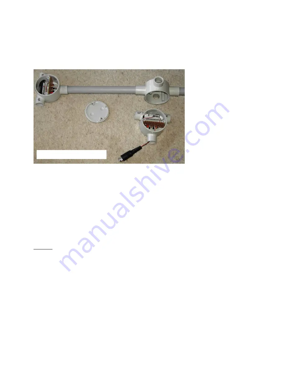
SAM-III Construction Manual
See last page for document and copyright information, File: SAM-III Magnetometer Construction.doc, Page 59
with sufficient separation. The third junction box at the bottom-right was used for test purposes and has
a short DIN cable originally for the SAM-II. Even though the photograph shows fittings with screw-type
covers, it is best to use glued fittings through-out to prevent water infiltration. Water or moisture will
ruin the sensor connectors.
The following information was provided by Darrel Emerson, who performed some undocumented
testing on the SAM-III sensors. If two sensors are parallel and too close, they tend to pull each other
onto the same frequency. In the parallel configuration, it is recommended that the sensors be separated
by at least 150 mm (6 in.) to minimize this effect. If the two sensors are at right angles to each other, the
pulling effect is much smaller. The effect also depends on the alignment with the Earth's field. If the
sensors are parallel, but one is rotated 180 degrees (so the pins are pointed in opposite directions), then
for most alignments with respect to the Earth's field, the two sensor frequencies are quite different, and
the pulling effect disappears. However, when their alignment with the Earth's field brings them both to
nearly the same frequency, the frequency pulling effect is strong.
Crosstalk: When the signal outputs from two or three sensors are carried in the same cable from the
magnetometer sensor location to the SAM-III processor module, the likelihood of crosstalk interference
is very high. The outputs are unbalanced and easily couple into adjacent cable conductors and become
part of the signal input from other sensors. There are at least a couple ways to solve the problem of
crosstalk interference. One is to install circuitry at both ends of the cable that converts the sensor signal
output to a balanced interface for transmission over balanced twisted pair cable and the other is to use
a separate cable for each sensor.
In the first method, an EIA-485 balanced line driver such as the Texas Instruments SN65LBC184
differential transceiver may be used. Information on this application is available on request. In the
second method, two shielded cables would be used in a 2-sensor installation, and three shielded cables
would be used in a 3-sensor installation.
Photo courtesy of Ray Schmidt.


