background image

2-1

SG888ZB Gateway Installation & Setup

Section 2

Install the SG888ZB Gateway in a central location close to a 120 VAC electrical receptical and free 

from radio frequency interference .  If the SG888ZB Gateway is intended to be connected to the 

internet, it must be close to an internet router for setup . Once the Gateway is connected to the 

internet, a wifi connection can be established and the Gateway can be moved to another location . 
STEP 1 . Confirm that all required parts are present in the Gateway package: Gateway with port 

cover, Ethernet Cable, USB Power Cable, USB Power Adapter and Installation/Quick Start Guide .

To operate wirelessly with an internet connection, SALUS wireless devices must use the SG888ZB 

Gateway.  This section provides guidance for installation, joining the Zigbee network with or without an 

internet connection and connection to the SALUS Smart Home application.

SG888ZB Gateway Installation

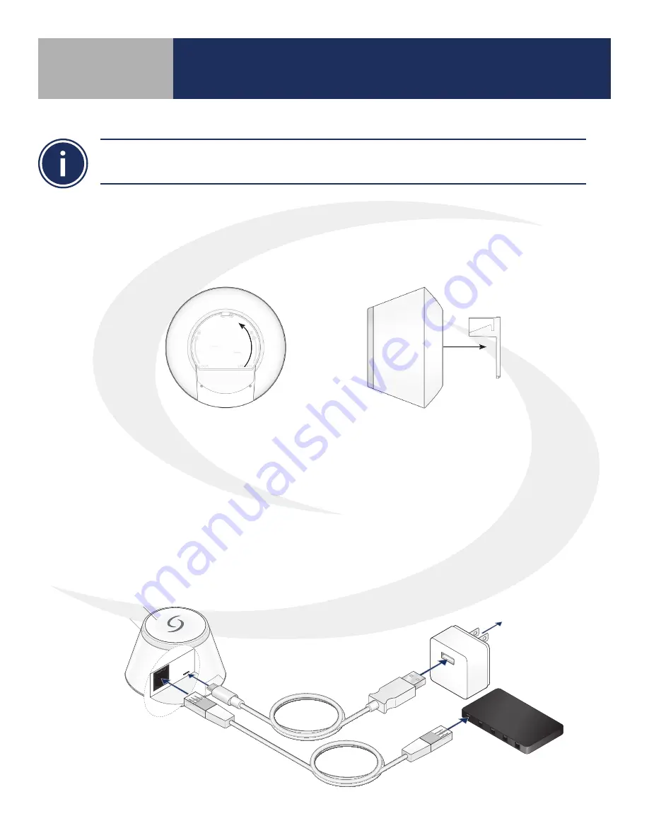
STEP 2 . Remove the port cover from the bottom of the Gateway by twisting it ¼ turn  

               counterclockwise 
STEP 3 .  If connecting the Gateway to the internet, attach the ethernet cable and the power cable to 

the gateway only, making sure it is within easy reach of a router or ethernet connection  


         a) For best results, DO NOT CONNECT the power cable to electrical power outlet until after  


              ethernet cable is attached to the router


         b) If no internet connection is intended, it is not necessary to attach the ethernet cable to  


              the Gateway

STEP 4 . Reattach the port cover on the Gateway
STEP 5 . Connect the ethernet cable to the Router if desired

STEP 6 . Plug the USB Power Cable into the USB Adapter and connect it to a 120 VAC outlet

Wireless Internet 

gateway

USB to 

micro USB cable

USB power 

adapter

To Internet router 

(supplied by  

network provider)

Plug into 120V outlet

Multi button

LED light ring

Ethernet cable

Summary of Contents for SG888ZB

Page 1: ...SMC GM CWSG M1 2019 11v1 2019 11 08 Connected Wireless System Guide Module 1 System Overview SG888ZB SALUS Smart Home Application...

Page 2: ...ashboard 3 2 4 Profile Settings My Profile 4 1 Logout 4 1 5 SALUS Smart Home Main Menu Devices 5 1 Gateway 5 1 All Devices 5 2 Add New Group 5 2 Edit Group 5 3 Add New Device 5 4 Edit Device 5 5 Devic...

Page 3: ...t home products including connected thermostats a smart home hub smart plugs water valve shutoff and door and window sensors A proven leader in the European market since 2003 Salus is currently expand...

Page 4: ...to provide a universal language for smart components to work together seamlessly and securely with or without an internet connection Section 1 SALUS Wireless System Components with SG888ZB Gateway Wir...

Page 5: ...ithout an internet connection and connection to the SALUS Smart Home application SG888ZB Gateway Installation STEP 2 Remove the port cover from the bottom of the Gateway by twisting it turn counterclo...

Page 6: ...nection to SALUS Smart Home services If successful the LED will turn blue If no interent connection is detected the LED will be red Connected to SALUS Smart Home services Not Connected to the Internet...

Page 7: ...r Android device for remote access to your home comfort system After downloading the application follow the steps in section 4 1 1 to create a user profile and set up an SG888ZB Gateway Online Applica...

Page 8: ...ess After 2 minutes the activation sequence will time out so make sure all required information is available The gateway serial number will appear once the connection is initiated Step 2 Choose the co...

Page 9: ...le to access gateway settings Step 3 Scroll to the bottom of the gateway setting screen and choose Scan for wifi Step 4 After the application finds available wifi networks choose the applicable networ...

Page 10: ...ortlessly manage your equipment and connected home from one screen Here you can pin equipment to the dashboard automate frequent tasks and monitor your gateway connection status and equipment states f...

Page 11: ...hoosing will unpin the icon from the dashboard Choosing the gateway name in the upper left provides access to options Edit the Gateway name by selecting Clicking will cause the SG888ZB LED to flash gr...

Page 12: ...ser can choose the country language clock format date format and temperature units Once the desired changes are made to the profile press An option to delete the user profile is also available Logout...

Page 13: ...d home from one screen Here you can pin equipment to the dashboard automate frequent tasks and monitor your gateway connection status and equipment states from a computer or smart device Devices Updat...

Page 14: ...the list of ungrouped equipment Clicking the icon toggles between pinned and not pinned to the dashboard All Devices Add manage or group equipment ADD NEW GROUP Groups are typically used in larger au...

Page 15: ...to edit the group or select Delete Group at the bottom of the screen Clicking a device tile icon enables access to the device status serial number and firmware version In addition the user can make c...

Page 16: ...equipment is ready for pairing press Scan for devices The SALUS Smart Home application will list of all devices ready for connection For each component to be connected click Press Give each device a u...

Page 17: ...Heat Cool Off or adjusting the target setpoint Note that the actual temperature is on the below the bar the target setpoint is on the top Clicking the device name in the upper left of the tile allows...

Page 18: ...the symbol expands the alert description providing details the current status and alerting criteria Click Add an alert to create a custom alert Enter a name for the alert and create an alert by pressi...

Page 19: ...to your dashboard Example Add a new Automation Choose add a new Automation Name the Automation and choose conditions and criteria for the automation Automations Configure Automated Commands If desired...

Page 20: ...r an email address and choose access level for new user Press The new user and their access level are displayed Select to Edit Resend Invitation or Remove Access for Users Update user level and press...

Page 21: ...6 1 Message Window Status Bar Section 6 Message Window The message window can incorporate a custom photo if desired In addition prompts to address issues can be displayed here...

Page 22: ...ttings choosing a different status can make changes to temperature setpoints and other settings For installations that don t follow a set schedule this is an easy way to change many settings at once b...

Page 23: ...ostat miniSmartplug and HVAC Thermostat Group Boiler System includes Receiver Relay Controller and Boiler Thermostat Automation One hour timer for miniSmartplug Current Error Indicates a low battery o...

Page 24: ...8 1 Icons and Device Settings Section 8 About this App Choosing About This App displays version and release date information about the software application...

Page 25: ...ently Asked Questions Clicking FAQ provides the latest information about topics that customers have asked about Contact Support Choosing from any screen will open your email application initiating dir...

Reviews: