53
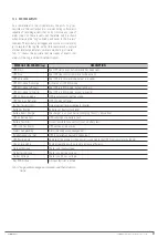
7.10. INFORMATION BUTTON
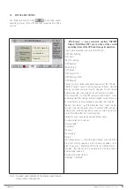
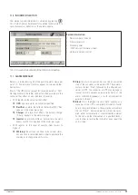
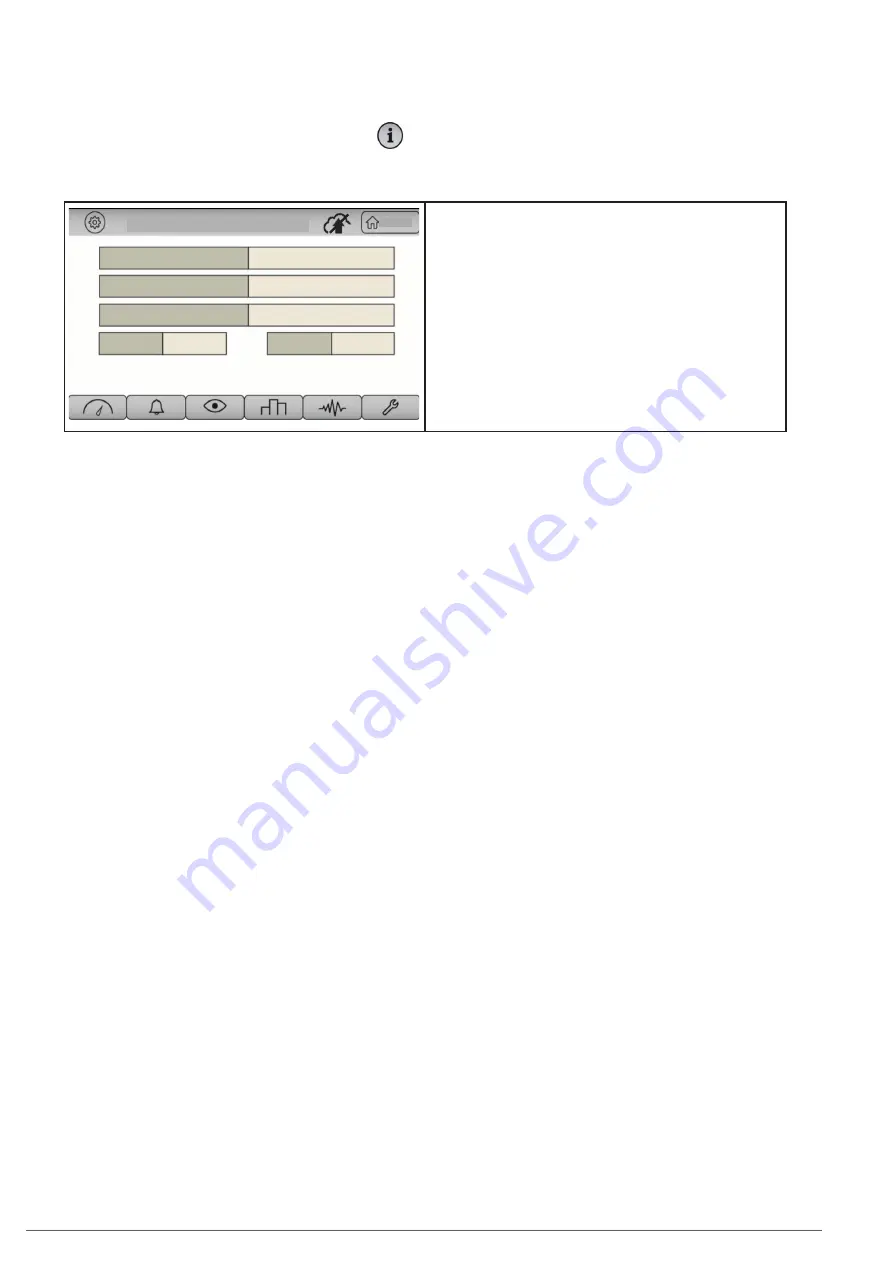
The internal system information is obtained by pressing
This information may be relevant for qualified technical staff, in
case of anomalous behaviour or the need to update.
INFORMATION
Home
SERIAL NUMBER
FIRMWARE VERSION
NOMINAL POWER
HIM VER
HW VER
0. 0
001.011.006.007.006
40 KVA
System information:
•
Serial number of the unit.
•
Firmware version.
•
Nominal power
•
"HIM" version (firmware screen).
•
Hardware version control.
Tab. 10.
Screen and contents of the Information button.
7.11. ALARM MESSAGES
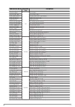
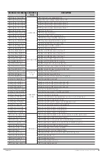
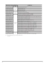
Below is a table showing all of the possible alarm messages
(see "7.3.- Alarms menu") that may appear on-screen and their
descriptions.
Most of the UPS alarms (except for those indicated as "N/A",
Not Applicable, in the table) can be classified according to the
converter they affect, or also their level of severity.
•
With regards to the converter they affect:
UPS
: a generic alarm, no converter specified.
Rectifier
: an alarm that affects the rectifier-PFC ("Rec"
appears in the alarm message).
Charger
: an alarm that affects the battery charger
("Charg." appears in the alarm message).
Inverter
: an alarm that affects the inverter or the static
bypass switch ("Inv" appears in the alarm message).
•
With regards to the level of severity (from lowest to
highest):
Warning
: the unit can continue in the current status,
but an action is recommended in order to eliminate the
warning or to change the unit's status.
Stop
: the alarm in question has caused an unwanted
stop of the converter or the entire UPS. These alarms
contain the text "Stop", followed by the affected con-
verter or UPS. The converter or UPS may manage to
recover normal operation automatically (retry, or the
alarm condition disappears), or with an intervention
external to the unit.
Block
: this is the highest level of alarm severity, as a
converter or the UPS is completely blocked (or faulty)
due to the specified reason. These alarms will contain
the text "Block". Normal operation will not be recov-
ered, either automatically or via intervention external
to the unit, and the intervention of a qualified techni-
cian in order to resolve the incident or even repair the
unit is likely.
SLC CUBE4
- UNINTERRUPTIBLE POWER SUPPLY SYSTEM
-
USER MANUAL
Summary of Contents for SLC CUBE4
Page 1: ...30 80 kVA USER MANUAL...
Page 66: ...66 SALICRU...
Page 67: ...67 SLC CUBE4 UNINTERRUPTIBLE POWER SUPPLY SYSTEM USER MANUAL...
Page 68: ...68 SALICRU...
Page 69: ...69 SLC CUBE4 UNINTERRUPTIBLE POWER SUPPLY SYSTEM USER MANUAL...


