39
Log In
Home
Load
2020-09-15
07:28:06
L1
231. 8
L2
233. 5
L3
232. 8
L1
229. 6
L2
229. 4
L3
230. 1
L1
0. 2%
L2
1. 0%
L3
0. 2%
Tot
0. 2%
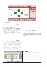
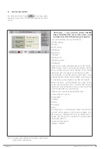
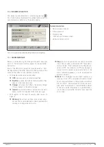
Fig. 35.
Main screen in bypass mode. The power flow
goes directly from the bypass input to the output,
via the static bypass switch. The rectifier and
charger continue operating.
The unit is now in bypass operating mode, described in
4.5.3
.
6.1.5. Procedure for transferring to normal mode from
bypass mode
Based on the situation described in
6.1.4
(manual forced bypass
mode), you can recover the normal operating mode of the UPS
via manual command.
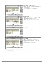
By accessing the "Status and Control", you can see that the
"UPS Status" shows "Rectif. Running". To switch to bypass
mode, you need to:
1.
Press the "Status and Control" icon
You are
on the screen described in
7.4
.
2.
Press the "INV/BYP Output" icon
3.
The "Output Control" pop-up box appears, with the "In-
verter" and "Bypass" options. Press "Inverter".
4.
The inverter should restart, and you will recover the
normal operating mode of the UPS.
"UPS Status" should
show "UPS Running", and on the main screen, the power
flow will correspond to the one shown in
Fig. 33
.
6.2. PROCEDURE FOR STOPPING THE UPS
This section describes the correct procedure for complete shut-
down of the UPS, leaving the loads without power, and the UPS
without any voltage at any of its input and output terminals
(and batteries, if any).
This procedure may be necessary in interventions to change the
installation, remove the UPS, replace it, etc.
With the UPS operating in normal mode (synoptic shown in
Fig. 33
, and in the "Status and Control" submenu you can see
that the "UPS Status" shows "UPS Running"), in order to shut it
down completely, proceed as follows:
1.
Stop the loads (or set their switches on the distribu-
tion board to "Off", if any) progressively.
2.
Press the "Status and Control" icon
You are
on the screen described in
7.4
.
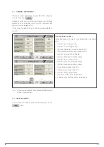
3.
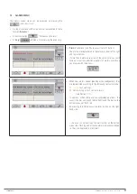
Press the "Start/Stop UPS" icon
4.
The "UPS Control" pop-up box appears, with the "Start"
and "Stop" options. Press "Stop".
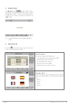
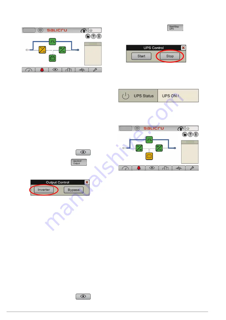
Fig. 36.
"UPS Control" pop-up window. Press "Stop".
5.
You can check the status on "Stand-By" of the UPS
.
The "UPS Status" field (Status and Control" submenu, see
7.4
) shows:
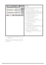
Stand-By
On the main screen, you can also check that the power flow
corresponds to that of the UPS when stopped, as shown in
Fig. 37
.
Log In
Home
Load
2020-09-15
07:28:06
L1
231. 8
L2
233. 5
L3
232. 8
L1
229. 6
L2
229. 4
L3
230. 1
L1
0. 2%
L2
1. 0%
L3
0. 2%
Tot
0. 2%
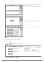
Fig. 37.
Main screen with the UPS stopped. The power
flow goes directly from the bypass input to the
output, via the static bypass switch, and all con-
verters are stopped.
6.
Set the switch corresponding to the UPS output on
the control panel (external) to "Off".
7.
Set the output switch of the UPS to "Off" (
Q2
).
8.
Disconnect the batteries:
a.
Units with internal batteries:
disconnect the 3-pole
battery connector (
Fig. 1
Detail A
,
on the front), or set
the battery switch to "Off" (
Q6
, on the front), as appli-
cable.
b.
Units with external batteries:
disconnect the 3-pole
battery connector (
Fig. 3 and Fig. 4 for 30 kVA and 40
kVA units,
on the back), or set the battery switch to
"Off" (
Q3,
Fig. 7 and Fig. 8 for 50 kVA, 60 kVA and 80
kVA units,
on the front), as applicable. Also, set the ex-
ternal battery cabinet switch to "Off"
(Q8
,
Fig. 10 and
Fig. 11).
c.
Units with shared internal and external batteries:
carry out points
a.
and
b.
described above one after
the other.
9.
Set the switch corresponding to the UPS input on the
control panel (external) to "Off".
If there is a separate
bypass line for the UPS, also set this switch on the control
panel to "Off".
SLC CUBE4
- UNINTERRUPTIBLE POWER SUPPLY SYSTEM
-
USER MANUAL
Summary of Contents for SLC CUBE4
Page 1: ...30 80 kVA USER MANUAL...
Page 66: ...66 SALICRU...
Page 67: ...67 SLC CUBE4 UNINTERRUPTIBLE POWER SUPPLY SYSTEM USER MANUAL...
Page 68: ...68 SALICRU...
Page 69: ...69 SLC CUBE4 UNINTERRUPTIBLE POWER SUPPLY SYSTEM USER MANUAL...


