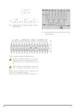
32
SALICRU
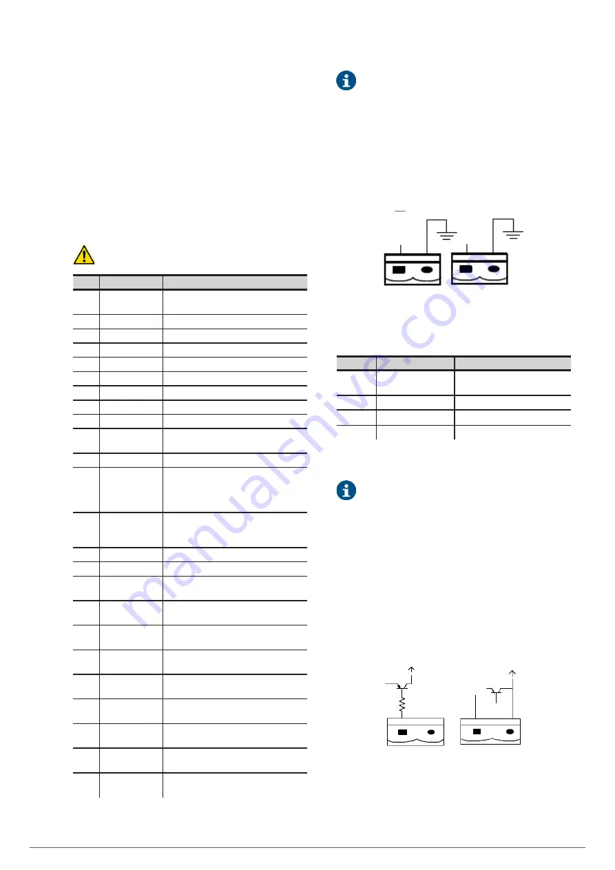
The UPS accepts an external signal from relays connected
through the relay interface and Phoenix terminals. Through
software programming, these signals are activated when these
contacts are connected to +24 V to earth. The cables connected
to the DRY terminal must be separated from the power
cables. In addition, these cables must have double insulation
with a typical cross section of 0.5 to 1.5 mm
2
for a maximum
connection length between 25 and 50 metres.
5.3.4.1. Relay interface.
The relay interface includes ports J2-J10
(1)
. The functions of
the relay interface ports are shown in Tab. 7.
(1)
Make sure that the rectifier and bypass input cables
have no voltage when connected.
Port
Name
Function
J2-1
TEMP_BAT
Battery temperature sensor (floating voltage
compensation)
J2-2
TEMP_COM
Common
J3-1
TEMP_ENV
Room temperature sensor
J3-2
TEMP_COM
Common
J4-1
EPO_NC
EPO activation when disconnecting from J4-2
J4-2
+24 V
+24 V
J4-3
+24 V
+24 V
J4-4
EPO_NO
EPO activation when connecting to J4-3
J5-1
+24 V_DRY
+24 V
J5-2
EXTER_BYPASS
‘NO’ auxiliary contact of external manual bypass
switch.
J5-3
GND
Common
J6-1
BCB_DRV
It provides a pulse signal of +24 V / 20 mA for
the remote control of the battery circuit breaker
through its coil. This signal activates the ‘Off’
switch
J6-2
BCB_CONT
Status of the BCB switch. Its normally closed
(‘NC’) auxiliary contact can be connected
between this pin and the GND
J7-1
GND
+ 24 V ground reference
J7-2
BCB_ONL
Not useful. Not implemented
J8-1
BYP_ALM_NC
Normally closed (‘NC’) contact, STATIC BYPASS
relay interface signal
J8-2
BYP_ALM_NO
Normally open (‘NO’) contact, STATIC BYPASS
relay interface signal.
J8-3
GND
Common for STATIC BYPASS relay interface
signal
J9-1
ALARM_NC
Normally closed (‘NC’) contact, GENERAL ALARM
relay interface signal
J9-2
ALARM_NO
Normally open (‘NO’) contact, GENERAL ALARM
relay interface signal
J9-3
GND
Common for GENERAL ALARM relay interface
signal
J10-1
UTI_FAIL_NC
Normally closed (‘NC’) contact, AC MAINS
FAILURE relay interface signal
J10-2
UTI_FAIL_NO
Normally open ('NO’) contact, AC MAINS
FAILURE relay interface signal
J10-3
GND
Common for AC MAINS FAILURE relay interface
signal
Tab. 7.
Functions of the relay interface ports.
The adjustable functions for each port can be modified
from the control software.
The default functions of each port are described as follows:
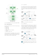
Output relay interface for ambient temperature detection
Ports J2 and J3 can detect, respectively, the temperature of the
batteries and the environment, and be used to monitor the envi-
ronment and compensate for the temperature of the batteries.
The diagram of ports J2 and J3 is shown in Fig. 41 and the
description in Tab. 7.
J3
J2
TEMP_ BAT
TEMP_ ENV
Fig. 41.
Connection diagrams of the temperature
detection ports.
Port
Name
Function
J2-1
TEMP_BAT
Battery temperature sensor
(floating voltage compensation)
J2-2
TEMP_COM
Common
J3-1
TEMP_ENV
Room temperature sensor
J3-2
TEMP_COM
Common
Tab. 8.
Description of J2 and J3.
A specific temperature sensor is required for
temperature detection (R25 = 5 kOhm, B25/50 = 3275):
check with the manufacturer or contact the maintenance
engineers when ordering.
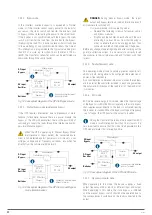
Relay interface for remote EPO
J4 is the input port for remote EPO. During normal operation,
24 V with NC and open the jumper between NO and
+24 V.
The EPO trips when opening the jumper between NC and +24 V
or when jumpering NO and +24 V (J4-3). The diagram of the port
is shown in Fig. 42 and the description in Tab. 7.
REMOTE_EPO_NO
REMOTE_EPO_NC
+24V
+24V
+24V_DRY
+24V_DRY
J4
Fig. 42.
Diagram of the relay interface for remote EPO.
Summary of Contents for SLC ADAPT Series
Page 1: ...SLC serie ADAPT 180 300 y 500 kVA UNINTERRUPTIBLE POWER SUPPLY UPS USER S MANUAL...
Page 12: ...12 SALICRU Fig 8 Front view of 10 slot cabinet 500 kVA 300 kVA at 3x208 V with closed doors...
Page 64: ...64 SALICRU...
Page 65: ...65 SLC ADAPT UNINTERRUPTIBLE POWER SUPPLY UPS USER S MANUAL...

