


36
SALICRU
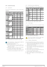
UPS input
Q1
Q2
Q4
Bypass input
Manual bypass
Cold Start
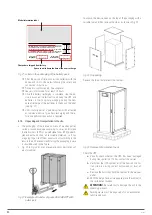
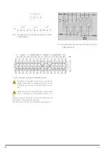
Fig. 50.
Position of the Battery Cold Start button on 500 kVA
devices.
3.
The system then starts following the three steps in section
6.1.1 and transfers to battery mode in 30s.
The LED indicators are shown in the following table:
Indicator
State
Indicator
State
Rectifier
Blinking red
Inverter
Green
Battery
Blinking green
Load
Green
Bypass
Blinking red
State
Red
Tab. 19.
LED Start sequence.
4.
Activate the load power supply output isolation. The system
works in Battery mode.
6.2. SHUTTING DOWN THE UPS.
To shut down the UPS completely, first ensure that the load has
been stopped correctly before opening the external battery cir-
cuit breaker, the main input circuit breaker (internal or external),
the bypass input circuit breaker (internal or external, if any) one
by one until the display turns off completely.
If the UPS is in bypass mode, also open the maintenance
bypass circuit breaker.
6.3. PROCEDURE TO TRANSFER BETWEEN OPERATING
MODES.
6.3.1. Transfer from Normal mode to Battery mode.
The UPS transfers to Battery mode immediately after the mains
voltage fails or the voltage drops below the predefined limit.
6.3.2. Transfer from Normal mode to Bypass mode.
1.
Enter the Operation menu, click on the ‘transfer to bypass’
icon
and the system will transfer to Bypass mode.
2.
Press the BYP button on the control panel for more than
two seconds and the system will transfer to Bypass mode.
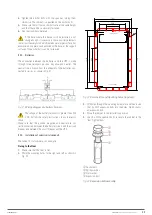
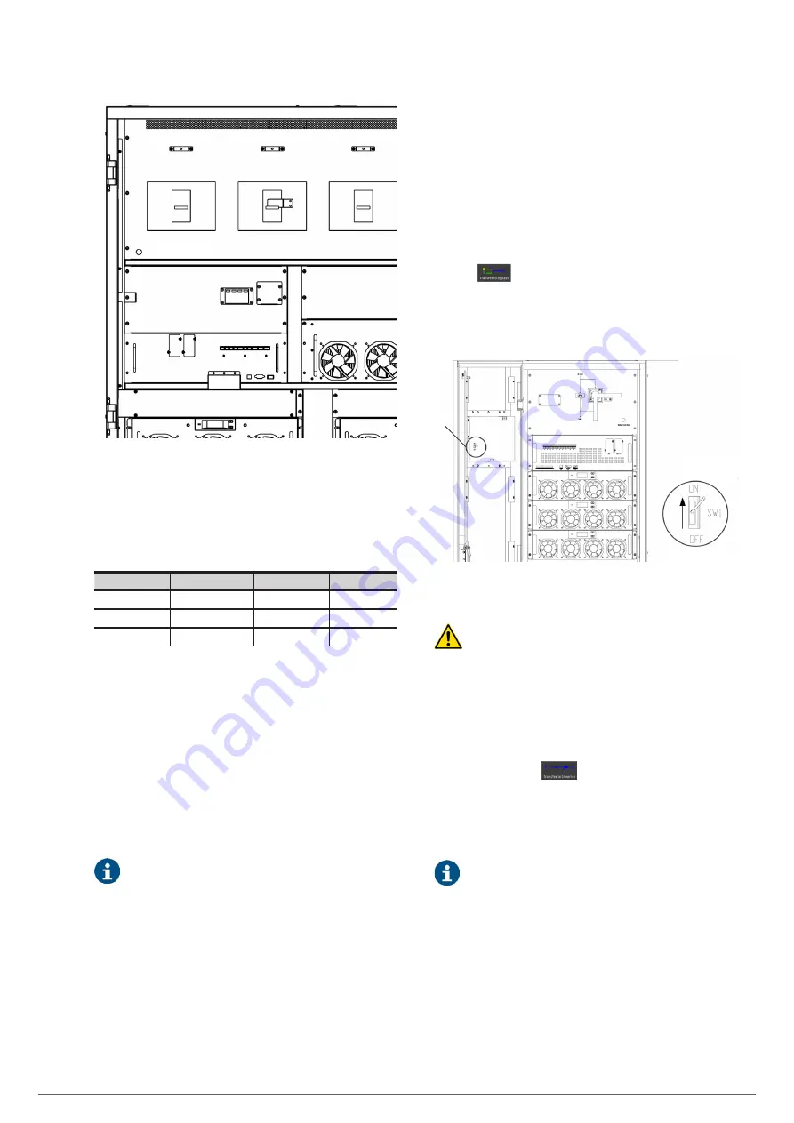
This requires the activation of the switch located behind
the front door, as shown in Fig. 51.
Activate the
switch
Zoom A
A
Fig. 51.
Activation of manual transfer from Normal mode
to Bypass mode.
Make sure that the bypass works normally before
transferring to Bypass mode, otherwise it could cause a
failure.
6.3.3. Transfer from Bypass mode to Normal mode.
There are two ways to transfer from Bypass mode to Normal
mode:
a.
Enter the Operation menu, click on the ‘transfer to
inverter’ icon
and the system will transfer to
Bypass mode.
b.
Press the INV button on the control panel for more than
two seconds and the system will transfer to Normal
mode.
Under normal conditions, the system will transfer to
Normal mode automatically. This function is used when
the frequency of the bypass is not synchronised or when
you need to manually transfer to Normal mode.
6.3.4. Transfer from Normal mode to maintenance Bypass
mode.
The following procedure is used to transfer the load from the
inverter output of the UPS to maintenance bypass, usually used
during repair or maintenance work.
1.
Transfer to Bypass mode following the instructions in
section 6.3.2.
Summary of Contents for SLC ADAPT Series
Page 1: ...SLC serie ADAPT 180 300 y 500 kVA UNINTERRUPTIBLE POWER SUPPLY UPS USER S MANUAL...
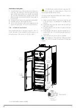
Page 12: ...12 SALICRU Fig 8 Front view of 10 slot cabinet 500 kVA 300 kVA at 3x208 V with closed doors...
Page 64: ...64 SALICRU...
Page 65: ...65 SLC ADAPT UNINTERRUPTIBLE POWER SUPPLY UPS USER S MANUAL...


