


8
Any DC Power-S has protections, nevertheless depending on
the power and voltage they can vary:
•
Input.
Circuit breaker protection for currents up to 160 A or fuses for
higher currents.
•
Batteries.
Circuit breaker protection, fuse switch or fuses plus switch,
depending on the battery current and voltage. The protection
will always be with two poles for a floating output voltage. Do
not break with load.
•
Output.
Output switch. Do not break with load.
Also the equipments can have different options, which the most
import are:
•
Batteries to provide back up time to the system. They can be
sealed or flooded PbCa type, NiCd, ...
•
DC outgoing distribution, by means of circuit breaker protec-
tions, fuse switch or fuse plus switch, depending on the bat-
tery current and voltage.
The protection will always be with two poles for a floating
output voltage. For outputs with the positive or negative
earthed, protections will always be single pole, in order to not
break the earthed pole.
As terminal block in the DC outgoing distribution with floating
output, will be used the own terminals of the protections.
For outputs positive or negative earthed, the terminal of each
single pole protection of the alive pole will be used as terminal
and the available rod of the earthed pole as general terminal.
•
Auxiliary contacts of the input, battery and output protections,
as well as the outgoing distribution.
Any protection can have a switch and independent auxiliary
contact, extended to an exclusive terminal strip for them.
•
Lighting arrestor.
•
Output dropping voltage.
•
Output voltage positive or negative earthed. As standard, it
is floating.
•
Extended communications.
•
Wireless-link communication.
•
Other IP protection degrees.
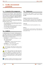
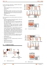
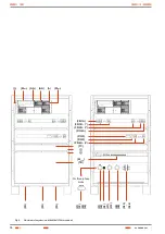
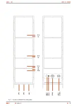
4.1. Equipment views.
(a)
(b)
(c)
(t
2
)
(BL
1
)
(AS
1
)
AC
Connections
Control
connections and
DC
(RV)
(RV)
Fig. 1.
Rectifier module view (M
rect
).
(M
cont
)
(F/Q1A)
(M
rect
)
(t
2
)
(RV)
(AS
1
)
(t
1
)
(AS
2
)
(t
3
)
(TB)
(RV)
(M
com
)
(GS)
(PF
2
)
(F/Q3) (F/Q2A)
(X
1)
(X
4)
(X5
)
(X
11
)
(X
12
)
(X
6)
(X9)
(PF
1
)
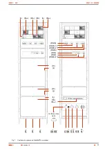
Fig. 2.
19'' subrack and 4U height view.
(M
cont
)
(F/Q1A)
(M
rect
)
(t
2
)
(RV)
(AS
1
)
(t
1
)
(AS
2
)
(t
3
)
(TB)
(RV)
(M
com
)
(F/Q3) (F/Q2A)
(X
1)
(X
4)
(X5
)
(X
11
)
(X
12
)
(X
6)
(X9)
(PI)
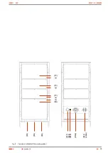
Fig. 3.
Table top case view.
USER MANUAL
Summary of Contents for DC POWER-S DC-10-S
Page 2: ......
Page 18: ...18 Case with casters dimensions Cabinet dimensions 605x605x1315 mm 605x805x1315 mm USER MANUAL...
Page 42: ...42 USER MANUAL...
Page 43: ...43 SALICRU...


