


26
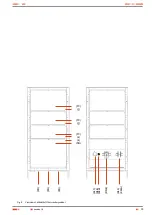
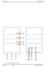
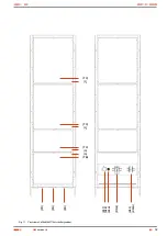
5.3. Structural diagram as an example.
Control Module
Communication Module
Outgoing distribution
IN
PU
T
O
UT
PUT
Low voltage
Device Contactor
Batteries
F/Q3
(F/Q1A)
(F/Q1B)
(F/Q1C)
(F/Q1*)
(F/Q2B)
(F/Q2C)
(F/Q2*)
(F/Q2A)
(F/Q2)
(F/Q6A)
(F/Q6B)
(F/Q6*)
Batteries can be fitted in the same cabinet of the rectifier,
in one or more separate cabinets or due to the configura-
tion in both cabinets. Battery protection is fitted in the
system cabinet and it is identified in the manual as
(F/Q3)
and the battery cabinet/s as
(F/Q8)
. Each cabinet will al-
ways have its own protection.
Regarding the protections, this manual uses the acro-
nyms (F/Q*), and to be referred to fuses (F) or to the cir-
cuit breakers (Q), which in accordance with the
regulations, they must be identified with those acronyms.
The letter (Q) is also used to identify a simple switch.
Fig. 16.
Structural example of a system.
USER MANUAL
Summary of Contents for DC POWER-S DC-10-S
Page 2: ......
Page 18: ...18 Case with casters dimensions Cabinet dimensions 605x605x1315 mm 605x805x1315 mm USER MANUAL...
Page 42: ...42 USER MANUAL...
Page 43: ...43 SALICRU...


