16
INSTALLATION
5.9. Additional battery installation
setup
1500/2000 VA and 3000 VA include external battery port
that allow to provide additional battery runtime. 1500/2000
VA model has no internal battery, and 3000 VA has de-
signed an internal battery inside the UPS.
Connecting battery cable to external battery port
may occur sparkle if adding up additional battery.
Follow the procedure to install additional battery as below:
5.9.1. 1500 / 2000 VA models
There are two external battery ports for each side of UPS
itself and battery pack.
1.
Connect the battery cable to the external battery port
of the rear of UPS.
2.
Then connect the supplied battery cable from ex-
tended battery module to the external battery port of
the rear of previous UPS.
3.
If continuing to add up extended battery pack, repeat
above steps.
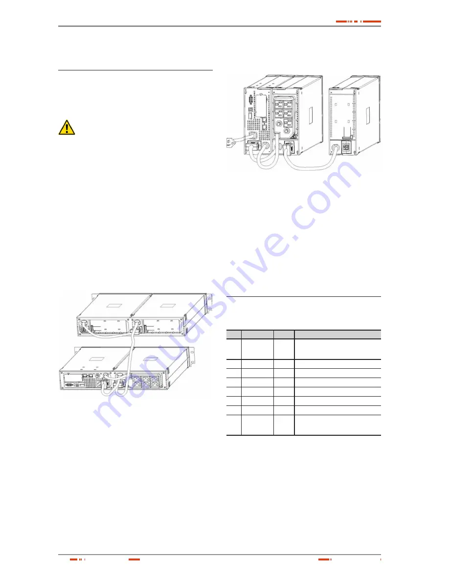
5.9.1.1. Additional battery connection in
rack form
Fig. 34.
Rear view of the additional battery connection
5.9.1.2. Additional battery connection in
tower form
Fig. 35.
Rear view of the additional battery connection
5.9.2. 3000 VA model
There is one external battery port for the UPS itself.
1.
Connect the supplied battery module cable from ex-
tended battery module to the external battery port of
the rear of UPS.
2.
If continuing to add up extended battery module, re-
peat above steps.
5.10. Communication Ports
5.10.1. RS232 + Optocouplers
Pin# Description
I/O
Function explanation
1
Low Battery
Output
Low Battery Output (*normally open,
pull to Pin#5 when battery low alarm in
battery mode)
2
TxD
Output
TxD
3
RxD
Input
RxD
4
DTR
Input
(tied to Pin#6)
5
Common
--
Common (tied to chassis)
6
DSR
Output
(tied to Pin#4)
7
RTS
Input
No connection
8
AC Fail
Output
AC Fail Output (**normally open, pull
to Pin#5 when battery low alarm in
battery mode)
Table 6.
DB9 Female (RS232 + optocouplers)
5.10.2. USB port: HID protocol
The USB and RS232 are unable to operate at the same
time. Either only USB or DB9 can connect with RS-232 at
one time, usually connecting with USB function is priority.
USER'S MANUAL


