background image

15

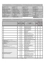
Heater

01h_Read_Coils

14

1

[ lt ]

 - Šildytuvo indikacija

[ fi ] -

 Lämmittimen käyntitila

[ en ]

 - Heater indication

[ de ]

 - Anzeige des Heizers

1-active, o-passive

16

Speed

06h_Write_Holding_Register

0

1

[ lt ]

 - Ventiliatorių greičio nustatymai

[ fi ] - 

Puhaltimen nopeusasetukset

[ en ]

 - Fans speed settings

[ de ]

 - Einstellbereich der Geschwindigkeit der Lüfter

0, 1, 2, 3

17

TsetPoint

06h_Write_Holding_Register

1

1

[ lt ]

 - Tiekiamo oro temperatūros nustatymas

[ fi ] - 

Tuloilman lämpötilan asetus

[ en ]

 - Supply air temperature set

[ de ]

 - Einstellbereich der Zuluft-Temperatur

0-30

18

RH_value

04h_Read_Input

13

1

[ lt ]

 - DTJ(100.1) drėgnumo jutiklio vertė

[ fi ] -

 Poistoilman kosteusanturin arvo

[ en ]

 - DTJ(100.1) humidity sensor value

[ de ]

 - Wert des DTJ(100.1) Feuchtigkeitssensors

0-99

19

Motor1

04h_Read_Input

15

1

[ lt ]

 - 1 ventiliatoriaus variklio vertė

[ fi ] - 

Moottorin 1 puhaltimen nopeuden arvo

[ en ]

 - Motor1 fan speed value

[ de ]

 - Geschwindigkeit des Motor des Lüfters 1

0-3

20

Motor2

04h_Read_Input

16

1

[ lt ]

 - 1 ventiliatoriaus variklio vertė

[ fi ] -

 Moottorin 2 puhaltimen nopeuden arvo

[ en ]

 - Motor2 fan speed value

[ de ]

 - Geschwindigkeit des Motor des Lüfters 2

0-3

[ lt ] 

- Temperatūros jutiklio vertė realiųjų skaičių formatu (-3.3E38 – 3.3E38), pvz., 0h->0C, 7FFFh->3276.7C, 8000h->3276.8, FFFFh->-0.1C

[ fi ] 

- Lämpötila-anturin arvon todellinen muoto (-3.3E38 – 3.3E38) esimerkki: 0h->0C, 7FFFh->3276.7C, 8000h->3276.8, FFFFh->-0.1C

[ en ]

 - Temperature sensor value 

real

 format (-3.3E38 - 3.3E38) example: 0h->0C, 7FFFh->3276.7C, 8000h->3276.8, FFFFh->-0.1C

[ de ]

 - Wert des Temperatursensors im Real-Format (-3,3E38 – 3,3E38), Bsp. 0h->0C, 7FFFh->3276,7C, 8000h->3276,8, FFFFh->-0,1C

21

Tlimit

04h_Read_Input

0

1

[ lt ]

 - Tiekiamo oro temperatūros vertė

[ fi ] - 

Tuloilman lämpötilan arvo

[ en ]

 - Supply air temperature value

[ de ]

 - Wert der Zuluft-Temperatur

Hex: E0

22

Texhaust

04h_Read_Input

1

1

[ lt ]

 - DTJ(100.1) temperatūros jutiklio vertė

[ fi ] - 

Poistoilman lämpötila-anturin arvo

[ en ]

 - DTJ(100.1) temperature sensor value

[ de ]

 - Wert des DTJ(100.1) Temperatursensors

Hex: E0

23

Textract

04h_Read_Input

2

1

[ lt ]

 - Šalinamo oro temperatūros jutiklio vertė

[ fi ] - 

Jäteilman lämpötila-anturin arvo

[ en ]

 - Exhaust air temperature sensor value

[ de ]

 - Wert des Abluft-Temperatursensors

Hex: E0

24

ToutDoor

04h_Read_Input

3

1

[ lt ]

 - Išorės oro temperatūros jutiklio vertė

[ fi ] - 

Ulkoilman lämpötila-anturin arvo

[ en ]

 - Ouside air temperature sensor value

[ de ]

 - Wert des Außenluft-Temperatursensors

Hex: FFEC

25

Twater

04h_Read_Input

12

1

[ lt ]

 - Grįžtamo vandens temperatūros jutiklio vertė

[ fi ] - 

Paluuveden lämpötila-anturin arvo

[ en ]

 - Return water temperature sensor value

[ de ]

 - Wert des zurückkehren Wasser-Temperatursensors

Hex: FFEC

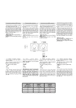
•  Elektrinis  pajungimas  gali  būti  atliktas  tik 

kvalifikuoto  elektriko  pagal,  galiojančius 

tarptautinius  ir  nacionalinius  elektrosaugos, 

elektros įrenginių įrengimo, reikalavimus.

•  Naudoti tik tokį elektros energijos šaltinį, kurio 

duomenys yra nurodyti ant įrenginio lipduko.

•  Maitinimo kabelis turi būti parenkamas pagal 

įrenginio elektrinius parametrus, jei įrenginio 

maitinimo linija yra toli nuo agregato, būtina 

įvertinti atstumą ir įtampos kritimą

•  Įrenginys būtinai turi būti įžemintas.

•  Sumontuokite  valdymo  pulta  numatytoje 

vietoje.

•  Nutieskite  pajungimo  kabelį,  esantį  FLEX 

pultelio  komplektacijoje,  tarp  valdymo  pulto 

ir ŠVOK agregato. Nuotolinio valdymo pultelį 

rekomenduojama  sumontuoti  atskirai  nuo 

jėgos kabelių.

Pastaba:

  Jei  naudojate  kabelį  kartu  su  kitais 

jėgos kabeliais, turi būti naudojamas ekranuotas 

su įžemintu ekranavimo šarvu pultelio kabelis.

•  Prijunkite kištuką (tipas RJ11) prie agregato 

RS485-1 lizdo. Kitą kabelio kištuką prijunkite 

prie valdymo pulto.

•  ähköliitännän  saa  tehdä  vain  pätevä 

sähköasentaja    asiaa  koskevien  kansain-

välisten  ja  kansallisten  turvavaatimusten 

sekä  sähkölaitteiden  asennusta  koskevien 

vaatimusten mukaisesti.

•  Käytettävän virtalähteen tulee täyttää laitteen 

kilvessä määritetyt vaatimukset. 

•  Virtajohto on valittava laitteen sähköteknisten 

tietojen mukaisesti. Jos laitteen jännitesyöttö 

on kaukana laitteesta, etäisyys ja jännitehäviö 

on huomioitava.

•  Laite tulee maadoittaa.

•  Asenna  ohjauspaneeli  sille  tarkoitettuun 

paikkaan.

•  Asenna  mukana  toimitettu  liitäntäkaapeli 

(FLEX-säädin)  ohjauspaneelin  ja  koneen 

väliin. On suositeltavaa asentaa ohjauspaneeli 

erilleen virtajohdoista. 

Huomautus: Jos johtoa käytetään yhdessä mui-

den virtajohtojen kanssa, on käytettävä suojattua 

ohjauspaneelin  johtoa,  jossa  on  maadoitettu 

häiriön suoja.

•  Kytke pistoke (RJ11-tyyppi) laitteen RS485-1- 

liitäntään. Kytke toinen pää ohjauspaneeliin.

•  Electrical connection can only be implemented 

by the qualified electrician in accordance with 

the applicable international and national elec-

trical safety requirements and requirements for 

installation of electrical devices.

•  Use  only  power  source  which  meets  the 

requirements specified on the device label.

•  Power supply cable should be selected based 

on the electrical specification of the device. If 

the device power supply line is far from the 

unit,  the  distance  and  voltage  drop  should 

be considered.

•  Device must be earthed.

•  Install  the  control  panel  at  the  designated 

place.

•  Install  the  supplied  connection  cable(FLEX 

controller)  between  the  control  panel  and 

the HVAC unit. It is recommended to install 

the control panel separately from the power 

cables.

Note:

 If cable is used together with other power 

cables, shielded control panel cable with earthed 

shield should be used.

•  Connect the plug (RJ11 type) to the RS485-1 

socket of the unit. Connect the other end to 

the control panel.

•  Elektrischer Anschluss  muss  durch  qualifi-

zierte Elektrofachkraft laut geltende interna-

tionale und nationale Bestimmungen für Ele-

ktroschutz und Einrichtung der Elektroanlagen 

ausgeführt werden.

•  Nur die Stromquelle gebrauchen, die auf dem 

Anlagenaufkleber angegeben ist.

•  Speisekabel  muss  laut  elektrischen  Param-

etern  der Anlage  gewählt  werden;  falls  die 

Speiseleitung der Anlage fern vom Aggregat 

ist, ist es nötig, den Abstand und Spannungs-

fall zu bewerten.

•  Die Anlage muss unbedingt geerdet werden.

•  Steuerpult muss auf dem vorgesehenen Platz 

montiert werden.

•  Anschlusskabel(FLEX), der ein Teil der Aus-

rüstung  ist,  muss  zwischen  dem  Steuerpult 

und  dem  HKLK-Aggregat  gelegt  werden. 

Empfehlenswert wird der Bedienpult getrennt 

von den Leistungskabeln montiert werden

Bemerkung:

  wenn  der  Kabel  mit  anderen 

Leistungskabeln  gebraucht  wird,  muss  ein 

abgeschirmtes  Pultkabel  mit  der  geerdeten 

Abschirmarmierung gebraucht werden.

•  Den Stecker (Typ RJ11) an die Aggregatsdose 

RS485-1  anschließen.  Den  anderen  Kabel-

stecker an den Steuerpult anschließen.

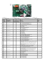
RS458_1 RS458_2

Summary of Contents for RIRS 1200VW EKO 3.0

Page 1: ...oidaan muuttaa RIRS 1200 VE VW EKO 3 0_P0037_BU_0001 REKUPERATORINIAI RENGINIAI L MM NTALTEENOTOLLA VARUSTETTU ILMANVAIHTOKONE AHU WITH HEAT RECOVERY L FTUNGSGER TE MIT W RMER CKGEWINNUNG RIRS 1200VE...

Page 2: ...rinio jungimo schema RIRS 1200VW EKO 3 0 32 Elektrinio jungimo schema RIRS 1200VW EKO 3 0 RHX 33 Gaminio prie i ros lentel 34 Sis lt Kuljetus ja varastointi 4 Kuvaus 4 Varotoimet 4 Osat 5 K ytt olosuh...

Page 3: ...oduct maintenance table 34 Inhalt Transport und Lagerung 4 Beschreibung 4 Schutzmassnahmen 4 Bestandeile des Ger tes 5 Betriebsbedingungen 5 Bedienung 6 Filter 6 Ventilator 6 W rmetauscher 7 Elektrohe...

Page 4: ...puso Naudokite tik tinkam i orin jungikl automatin antsrovio saugikl r modelio lipduke nurodyt galingum ir nominalios srov s dyd Parinktas maitinimo laidas turi atitikti renginio galingum Niekada nena...

Page 5: ...5 1 Geh use 2 Schaltschrank 3 Abluftfeuchte und Temperaturf hler 4 Druckrelais der Abluftfilter 5 Druckrelais der Zuluftfilter 6 Abluft Ventilator 7 Frischluft Filter 8 W rmetauscher 9 Zulufttemperat...

Page 6: ...ance with the readings of filter contamination sensor Sensor PS 600 is integrated in the unit Verunreinigte Filter erh hen die Druckverluste d h ein geringeres Luftvolumen gelangt in die R ume Die Fil...

Page 7: ...VAARA L mm nsiirrint ei saa k ytt ilman suodattimia Be sure the unit is disconnected from power source before performing any maintenance or repair Proceed to maintenance and repair after any rotation...

Page 8: ...ug X22 con nection of electrical heater control bord and connect control socket X22 marked red with socket X34 marked blue see System ad justment guidlines Electrical water sup ply air heater Das Elek...

Page 9: ...zuluft galia srov nimellisteho virta power current Nennleistung Nennstrom kW A 0 415 2 81 apsisukimai py rimisnopeus speed Drehzahl min 1 3400 valdymo signalas ohjaussignaali control input Steuerungs...

Page 10: ...iekimo Tuloilma supply Zuluft F7 Plotis Leveys Width Breite L mm 745 Auk tis Korkeus Height H he H mm 350 Gylis Syvyys Depth Tiefe L2 mm 46 Filtro modelis Suodatinmalli Filter model Filter Modell MPL...

Page 11: ...st be mounted on the flat horizontal surface so tas not to lean Pic 01 Before connecting to the air duct system the connection openings of ventilation system air ducts must be opened If necessary the...

Page 12: ...T1 Nestel mmittimen j tymissuojan termostaatti TV Nestel mmittimen j tymissuojan anturi VV J hdyttimen 2 tieventtiili M4 L mmittimen l mp johtopumppu M5 Nestej hdyttimen venttiilin toimilaite 24 V AC...

Page 13: ...li voidaan vaihtaa eli se voidaan asentaa niin ett ulkoilman tu loaukko on vasemmalla puolella tai niin ett ulkoilman tuloaukko on oikealla puolella Vaihto tehd n vaihtamalla takaluukun ja etuluukun p...

Page 14: ...maisen kanavan nenvaimennin Circular duct silencers Rohrschalld mpfer OC Atvamzdis Outlet Cover Imus leikk Branch pipe Outlet Cover Ausblas Ansaugstuzten Outlet Cover AP Apkaba Pantaliitos Clamp Verbi...

Page 15: ...iekiamo oro temperat ra gali b ti reguliuo jama pagal tiekiamo arba i traukiamo oro tem perat ros jutiklio i matuot ir vartotojo nuotoli niame valdymo pultelyje nustatyt temperat r Vartotojo nustatyta...

Page 16: ...5 3 for details on selecting this feature When control algorithm of the extracted air sensor is selected then supply air temperature is adjusted based on estimated additional received heat heat emitte...

Page 17: ...protection of the water heater During voltage loss supply air valve is closed immediately It does not automatically reset and should be reset restarted from the control panel b When the device has the...

Page 18: ...vice will work based on the latest changes of settings As set in the factory the device will operate if no faults are present based on the latest panel settings in case the panel or BMS network or eve...

Page 19: ...iklio pavojaus signalas fi Tuloilman l mp tila anturin h lytys en Supply air temperature sensor alarm de Zuluft Temperatursensor Alarm 1 active o passive 9 RH 01h_Read_Coils 9 1 lt DTJ 100 1 dr gnumo...

Page 20: ...tarp valdymo pulto ir VOK agregato Nuotolinio valdymo pultel rekomenduojama sumontuoti atskirai nuo j gos kabeli Pastaba Jei naudojate kabel kartu su kitais j gos kabeliais turi b ti naudojamas ekran...

Page 21: ...kin Q ON asentoon kuvan 5 mukaisesti joissain mal leissa turvakytkimen ulkon k saattaa poiketa kuvasta NOTE The remote control panel can be con nected and or disconnected only after discon necting the...

Page 22: ...etettava 5 C seen Before commissioning device launching and adjustment works must be done only by qualified and trained personnel Automatic control system of the ventilation unit must be properly adju...

Page 23: ...t at electrical connections of the unit St rung in elektrischen Verbindungen Anschl s sen des Aggregats lt Patikrinti jung i lizdus ir ki tukus sitikinti ar sujungiamieji kontaktai nepa eisti fi Tarka...

Page 24: ...funktioniert Tiekiamo PV arba i traukiamo IV oro ventiliato riaus gedimas Vika tuloilman tai poistoilman puhaltimessa Supply PV or extracted IV air fan fault St rung des Ventilators f r Zuluft PV ode...

Page 25: ...alissa toimintatilassa ymp rist n kapillaaril mp ti lan pit isi olla korkeampi kuin termostaatin ilmaisema koskettimen pit isi olla kiinni liit nt jen 4 ja 1 v lill kuva 2a Selvit onko tuloilman l mp...

Page 26: ......
Page 27: ...16A 100 X29 Elektrinis pa ildytuvas rotorius S hk inen esil mmitin roottori ON OFF 230V 50Hz Electric preheater rotor ON OFF 230V 50Hz Elektrovorheizer Rotor EIN AUS 230V 50Hz O 16A 100 X12 Esamo gre...

Page 28: ...uvo cirkuliacinio siurblio valdymas DX j hdyttimen tai nestel mmittimen l mp johtopumpun s t DX cooler or water heater circulatory pump control Kontrollieren des Freonk hlers bzw der Zirkulationspumpe...

Page 29: ...iklis Poistoilman l mp tila anturi Extract air temperature sensor Abzugsluft Temperatursensor AI X38 2 COM X40 1 5V X40 2 I traukiamo oro santykin s dregm s jutiklis Poistoilman kosteusanturi Extract...

Page 30: ...condition We therefore extend to the original purchasers the following Warranty for the period of two years from the original date of purchase If equipment is found to have been damaged in transit a...

Page 31: ...ON OFF L X37 TL N PE L1 1 3 4 2 LOW X32 1 COM X32 4 HIGH X32 2 TIMER X32 3 COM X33 1 MID X33 2 CHIL X33 9 COM X33 10 BOOST STOP NO START NC A2 A1 R1 8 7 X16 3 ALARM X33 11 COM ANTI F Fan fall 1 2W max...

Page 32: ...X32 4 HIGH X32 2 TIMER X32 3 COM X33 1 MID X33 2 CHIL X33 9 COM X33 10 BOOST STOP NO START NC A2 A1 R1 8 7 X16 3 ALARM X33 11 COM ANTI F Fan fall 1 2W max 4 5 6 10 9 X16 4 24 1 2W max Fan run 11 12 C...

Page 33: ...23 COM T set 26 24V DC 27 intput 0 10V DC 28 GND Transmitter 2 24 VDC P 29 X16 7 30 31 1A 2 1 F3 N L M4 PE 1f 230V AC 32 X16 8 33 34 24VDC 0 10VDC M6 G Y 0 0 GND Y 0 10V G 24VDC X16 9 35 36 T1 TV X16...

Page 34: ...replacement Filterwechsel Kas 3 4 m nesius 3 4 kuukauden v lein Every 3 4 months Alle 3 4 Monate PASTABA Produkt sigij s asmuo privalo pildyti Gaminio prie i ros lentel HUOMAUTUS K ytt j n on t ytett...

Reviews: