9
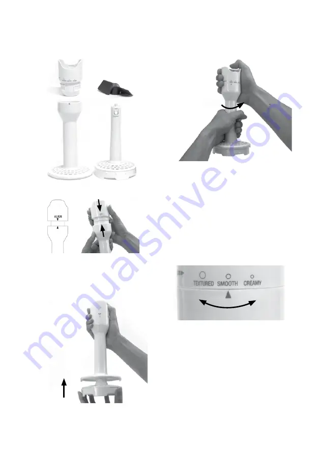
ASSEMBLING THE MASHER LEG
1. The masher leg is an assembly of 4 parts,
the gearbox, blade, outer leg, and inner leg.
2. Align the outer leg and gearbox as shown.
3. Once aligned, hold the outer leg and
gearbox firmly with one hand. Insert the
inner leg and push up until it clicks and
locks into place.
4. Rotate gearbox anti-clockwise while
holding the outer leg. Rotate until it clicks
and locks into place.
5. Refer to instructions in previous section to
attach the mashing leg with the motor body.
Push together until it clicks and locks.
6. Position blade on the underside of mashing
head, and lock by rotating anti-clockwise.
IMPORTANT
Blade will only attach when the mashing leg
is attached to the motor body.
7. Select the desired setting on the variable
mashing leg: textured, smooth or creamy.
Summary of Contents for the Control Grip All In One
Page 1: ...the Control Grip All In One Instruction Book BSB530UK...
Page 27: ......


