background image


13 


OPERATION AND ADJUSTMENT 
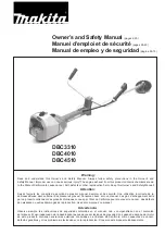


FIGURE 18   


        FIGURE 19 


12. Banding Laminate Strips 
 

Banding laminate strips is done by placing a strip into the slot, similar to the tape placement.  The 
strip should be approximately 1” longer than the panel being banded.  Because the guillotines 
cannot end trim the laminate they must be disabled and the trimming of the ends done manually. 
 
To disable the rear guillotine, turn off the toggle switch located on the side of the main power box 
(

FIGURE 18). 


To disable the front guillotine with the power turned off, open the outfeed end access door and 
remove the return spring from the ¼” attachment rod and push the knife closed manually 
(

FIGURE 19)

.  

NOTE:  Be sure power is off while doing this.

 The guillotine will stay closed 

and out of the way of the laminate strip passing by.  

Note: 

A buzzing noise may be heard as the 

panel passes through but this is normal and when returning back to normal edgebanding 
operation.  Reconnect the spring for banding tape. 

Toggle Switch 

Router  Fuses 

Summary of Contents for 72GP

Page 1: ...s Manual Model 72GP Safety Speed Manufacturing 13943 Lincoln Street NE Ham Lake MN 55304 Tel 763 755 1600 Fax 763 755 6080 w w w s a f e t y s p e e d c o m sales safetyspeed com Copyright 2011 Safet...

Page 2: ...ight Adjustment 9 Control Panel 10 Operating Temperature 11 Glue Application Adjustment 11 Glue Level 11 Top and Bottom Edge Trim Fine Adjustment 12 Front Tape Length Adjustment 12 Rear Tape Length Ad...

Page 3: ...ent that is determined to be defective Such repair or replacement is limited to providing satisfactory replacement parts from the factory Safety Speed assumes no responsibility for making repairs on s...

Page 4: ...h current safety standards Wear hearing protection during extended use and a dust mask for dusty operations Hard hats face shields safety shoes etc should be used when specified or necessary Keep a fi...

Page 5: ...mponents sharp and clean Follow instructions for lubricating and changing accessories Periodically inspect tool cords for damage Have damaged parts repaired or replaced 22 MAINTAIN LABELS AND NAMEPLAT...

Page 6: ...IGURES 1 2 Be sure to replace bolts after strap has been removed FIGURE 1 FIGURE 2 3 Remove protective packing from inside Glue Pot and apply Glue Pot Lid found inside the box packaged with the machin...

Page 7: ...ebris FIGURE 5 FIGURE 6 7 Confirm levelling pads are securely in the base of the machine Level the machine front to back and side to side NOTE Machine must sit level to ensure that the glue pot moves...

Page 8: ...ith approximately 1 16 clearance using the plastic thumb knob to lock into place 2 Adjusting Tape Guide FIGURE 10 A With power switch turned off advance tape until it passes all the way through the ta...

Page 9: ...t Adjust FIGURE 12 A Take a sample of panel to be banded and lay it on the tabletop slides parallel to the front of the power feeder B Lower the feeder until the top of the panel is approximately 2MM...

Page 10: ...completely turning the feeder switch off will engage the standby temperature The lower SV value will change to indicate the lower temperature Turning the feeder switch on will reinstate the normal op...

Page 11: ...w Turning the glue adjustment screw clockwise will increase the amount of glue and turning it counter clockwise will reduce it This adjustment is done while at operating temperature and while auger is...

Page 12: ...panel TIP To get the best results be sure knife components are free of debris 11 Rear Tape Length Adjustment Figure 17 Periodic adjustment may have to be made due to many factors Panel squareness fee...

Page 13: ...n off the toggle switch located on the side of the main power box FIGURE 18 To disable the front guillotine with the power turned off open the outfeed end access door and remove the return spring from...

Page 14: ...r is perpendicular to the machine top and retighten screws NOTE The auger is factory aligned and tested however due to shipping it may have moved slightly and need minor alignment following these proc...

Page 15: ...lowering feeder without loosening infeed locking handle it can be re levelled by the following procedure A Loosen feeder mount cross bolt just slightly with a 9 16 wrench FIGURE 25 just enough so that...

Page 16: ...rature controller to avoid damaging components Contact Safety Speed for technical information necessary to make these changes B Once the machine is at operating temperature see section on Operating Te...

Page 17: ...ating hold a damp cloth to the bottom of the belt to remove build up that may affect belt traction and feed consistency WARNING Use caution when doing this and keep hands away from trim bits and end c...

Page 18: ...18 D Electrical Supply Diagram 4 Wire 1 Hot Black 3 Neutral White 5 Hot Red Green Ground Black White Red Green...

Reviews: