background image

© Safe Fleet | 2020 | All rights reserved | Part #: 700-1234 R1

DH4 Installation Guide

p. 14

DH4 Operation

Video Flagging

Flagging and Event

Under normal conditions, the DVR is continuously recording when the vehicle ignition is on. If something happens that should 

be flagged for review, press the RGY button to ensure the event is easy-to-find later.

Each time you flag an event with the RGY Button, the system places a special Alarm tag on the video, as well as the date and 

time. Upon playback, any triggered Alarms are displayed, and the reviewer can jump directly to the tagged sections and see 

the associated video (details depend on how the DVR is configured). For full-featured video review, searching, and archiving, 

we recommend Evidence Manager. The software is supported on a Windows-based computer. For more information, see the 

Evidence Manager User Guide

 on the Safe Fleet Community.

If your organization uses one of our video management applications (Commander or Depot Manager), tagged video can be 

automatically downloaded and made available to reviewers when your vehicle returns to the depot. Commander provides 

these capabilities using a cloud-based architecture designed to simplify total deployment management and upkeep, while 

Depot Manager provides the same capabilities in a non-cloud or local deployment. For more information, see the Commander 

and Depot Manager guides on the Safe Fleet Community.

 

RGY Button 

The RGY Button must be installed in the vehicle in 

order  to  flag  video.  For  more  information,  contact 

Safe Fleet.

Using On-screen Keyboards

Entering Data

Before you proceed, you will need a portable video monitor and a USB mouse connected. To use a mouse for entering text 

and numbers in OSD fields:

1. 

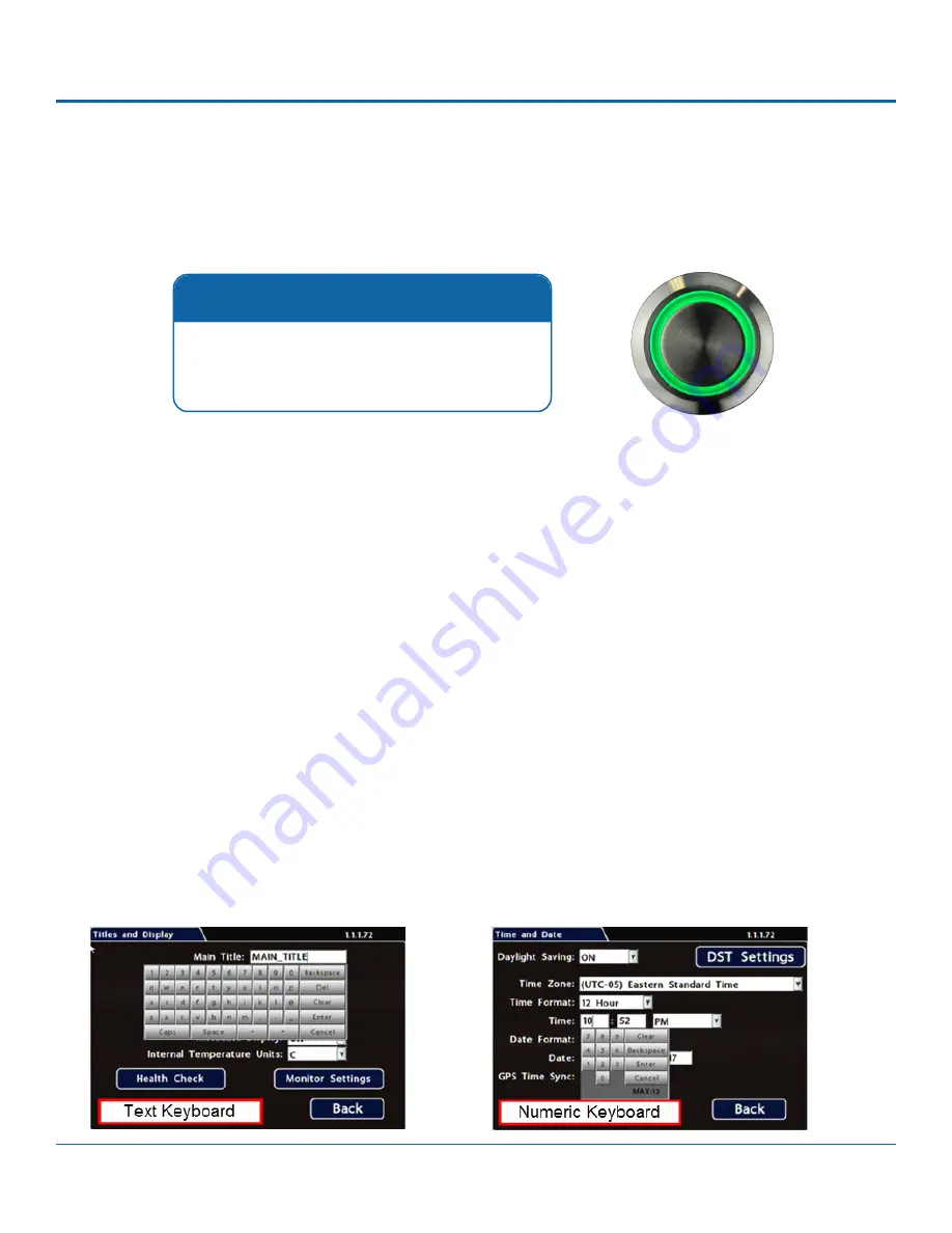
Click in an OSD field that accepts text or numbers as input. The on-screen keyboard (text or numeric, as shown below) 

pops up on the screen.

2.  Click text or numbers to enter values with the virtual keys. Cancel closes the keyboard without saving changes.
3.  When you're done, click Enter to save changes and close the keyboard.

Summary of Contents for DH4

Page 1: ... Safe Fleet 2020 All rights reserved Part 700 1234 R1 Installation Guide DH4 4 Channel Hybrid DVR ...

Page 2: ... Safe Fleet 2020 All rights reserved Part 700 1234 R1 this page intentionally blank ...

Page 3: ...ng 14 Using On screen Keyboards 14 Health Check 15 DH4 Administration 16 Accessing the On screen Display 16 Working with Video 19 DH4 Basic Configuration 22 Setting up the DVR 22 Time Date Tab 24 Title Display Tab 25 Camera Settings 27 Configuring Signals 28 Alarm Settings 30 Copying DVR Configuration 32 DH4 Advanced Configuration 34 Configuring Recording Settings 34 Network Settings 36 Advanced N...

Page 4: ...r Configuration equipment For on screen configuration portable video monitor and mouse For vMax Web configuration laptop and an Ethernet cable System Components The typical installation components are listed below DH4 video recorder with hard drive locking front cover cable cover fasteners and mounting plate Power harness PH2X2MFJR Camera Options Analog High Definition cameras HD3Q HD3W HD3U HD3S ...

Page 5: ... 6 1m RGY extn harness 060 1197 optional 065 1010 20 ft 6 1m 3 wires 1A 10A POWER Black Battery Negative Yellow Vehicle Ign 12V Red Vehicle 12V 4 Standard Resolution and or High Definition Cameras Adapter Harness 3 5 wires RGY BUTTON 1x5 Microfit SIGNALS Black Left Turn Green Stop Red Brake Signal Brown Warning White Right Turn G SENSOR optional g sensor mdl Rear Vision System Optional Reserved 2x...

Page 6: ... DVR in either a horizontal or vertical orientation or hung right side up but NOT upside down CLEARANCE Allow sufficient clearance of at least 6 inches in front of the DVR and 2 inches to each side for removal of the security front cover and easy access to the hard drive and USB ports Allow sufficient clearance behind the DVR for camera cables mounting cables Ethernet cables and power cables MOUNT...

Page 7: ...nd rotate a quarter turn to lock the drive 4 Use the mounting plate to mark the desired position of the DVR and drill the four mounting holes 5 Fasten the mounting plate to the mounting surface with the four self drilling screws 6 Slide the rear bottom edge of the DVR into the spring tab on the back edge of the mounting tray 7 Attach the front bottom edge to the front of the DVR using the two pan ...

Page 8: ...DVR rear panel SIGNALS socket 2 Connect the 5 signal input wires 3 Connect the Adapter s 1x5 Microfit to the RGY button extension harness optional For more information see the System Diagram on page 5 To install the Expansion Harness 1 Connect the 2x4 Microfit connector to the EXPANSION socket on the DVR 2 Connect the 1x4 Microfit to the Student Tracking harness optional 3 Connect the 2x3 Microfit...

Page 9: ...age complete 6 Once the update is finished the DVR automatically restarts 7 Remove the USB memory device Completing Upgrade After restarting the DVR may take up to 3 minutes to load and complete the upgrade Wait until the DVR finishes loading Firmware Updates Firmware controls how DVR features operate including the Playback and Configuration menu displays Technical Support may direct you to instal...

Page 10: ... up the DVR from the vehicle ignition Configure the DVR to required specifications locally using the mouse and monitor or remotely with a Web browser via WiFi or Ethernet using a PC For more information see Basic Configuration on page 21 Confirm the ERR HDD and PWR status indicators on the DVR front panel work properly Confirm that all cameras and audio sources operate properly Test audio video re...

Page 11: ...ates when the DVR is accessing the drive ERR illuminates solid red when one of the following faults occurs video loss HDD unlocked fan error PoE overload 5 Mouse Port connection for USB mouse shown with slot dust cover 6 USB Port shown with slot dust cover supports USB devices used to copy video and audio information export video clips update DVR firmware import export configuration data and archi...

Page 12: ... input for optional G force sensor unit 8 EXPANSION connector for communicating with other devices 9 SIGNALS connector for signal harness with an optional adapter for the RGY button 10 IP EXP RJ 45 Ethernet LAN connector for a laptop or other accessories 11 POE LAN dedicated Ethernet port for connectivity with Smart Reach Lite wireless bridge and other equipment POE LAN Port is 12 volt In addition...

Page 13: ...green Color Recorder Status Examples Green Recording normal no video loss from any camera no problems with recording operation Routine operations including recording warming up booting shutting down Yellow Recording video loss recording but experiencing video loss from one or more cameras Video loss on any or all channels 1 Red Not recording system unable to record due to an abnormal condition Not...

Page 14: ... video management applications Commander or Depot Manager tagged video can be automatically downloaded and made available to reviewers when your vehicle returns to the depot Commander provides these capabilities using a cloud based architecture designed to simplify total deployment management and upkeep while Depot Manager provides the same capabilities in a non cloud or local deployment For more ...

Page 15: ...tting HARD DRIVE HOURS The number of hours the drive has been powered on since it was manufactured GENERAL HEALTH Result of the drive subsystem self check green indicates normal operating status while red means a drive failure was detected GPS Connectivity indicator green when a GPS location fix is achieved otherwise red LAN FRONT Connectivity indicator green when a cable is connected from the DVR...

Page 16: ...ommend Evidence Manager The software is supported on a Windows based computer For more information see the Evidence Manager User Guide on the Safe Fleet Community To use the On screen Display 1 Connect a portable video monitor to VIDEO OUT on the DVR front panel 2 Plug a USB mouse in a USB socket on the front of the DVR 3 Power up the DVR The DVR splash screen appears briefly The system displays l...

Page 17: ...T MID HD SIZE Formatted size of the primary recording media in gigabytes GB The second value in square brackets is the size of the SD card OFF indicates the storage media is not present HD USED Percentage of primary media storage spaced used by recorded video The second value in square brackets indicates the percentage of recorded video on the SD card OFF indicates the storage media is not present...

Page 18: ...IME AND DATE Current recorded time and date GPS COORDINATES If GPS is connected the actual coordinates latitude longitude and heading appear If GPS is connected but the satellite signal is not being received zeros are displayed AC ALARM COUNT Number of alarms triggered Resets to 0 when DVR is restarted FAN Highlights to indicate trouble with the DVR fan GSN Highlights when external G Sensor is con...

Page 19: ...play menus 1 Connect a portable monitor and USB mouse and power up the DVR For more information see DH4 Administration Accessing the On Screen Display 2 Right click anywhere in the OSD view to access the Main Menu 3 Click Playback 4 In the center of the Playback View click the Show Hide icon The Playback Toolbar appears 5 Click the icons to browse video and archive clips Multi camera View Playback...

Page 20: ...orward Fast forwards playback With playback paused each click advances the video by one frame G Individual Camera Multi view Displays a single camera 1 2 3 or 4 or multi view all 4 cameras H Audio Cycles through Audio for channel 1 2 3 4 5 or 6 I Metadata Text Overlay Turns on text overlay temperature system voltage GPS data if recorded speed date and time For more information see Metadata Details...

Page 21: ...screen Keyboards 3 If desired use the Search Only pull down and submenus to specify Alarms Signals or System Events to search 4 Click Search If Search Only is set to Time Playback starts from the specified time and date if the video exists on the hard drive If you select Alarms Signals or System Events The DVR retrieves a list of recorded video segments containing the specified event type Select a...

Page 22: ...creen Display menus with small interface differences as well as video search playback and archiving features Logging in to the DVR with a Web Browser requires the proper network configuration to establish a connection and a browser extension to display the user interface Plug an RJ 45 Ethernet cable into the front panel LAN port or connect remotely over a network if you have Smart Reach wireless a...

Page 23: ... and Signals Speed If the DVR is used in Canadian fleets select the KPH speed units Alarms and Signals DH4 external G Sensor If a G Sensor is installed Calibrate Network If an external Smart Reach WiFi bridge is used set addresses as instructed by an IT administrator Use the IP address shown to communicate with the DVR over the network with vMax Web Network Advanced If a Smart Reach Cellular modem...

Page 24: ...en Keyboards 3 Click Back to save the settings and return to the Configuration menu MENU ITEM DESCRIPTION Daylight Saving Leave ON and at default dates unless in an area that does not use daylight savings e g Arizona Saskatchewan Click DST Settings and ensure the Start End dates and times apply to your location ON Time Zone Select your local time zone UTC 05 Eastern Standard Time Time Format Choos...

Page 25: ...Title Enter the bus number MAIN_TITLE Titles Display Display hide Main Title and Camera Titles ON OFF Time Date Display Display hide time and date ON OFF Record Status Display Display hide DVR recording status LIVE showing camera feeds RECORD storing video V LOSS video loss ON OFF System Data Display Display hide DVR system metadata HDD Size primary recording media Full HDD primary media Voltage F...

Page 26: ... temperature inside the DVR F Fahrenheit C Celsius Signals When a signal activates the Label is displayed For more information see DH4 Configuration Signals GPS Coordinates Latitude longitude and elevation If GPS is connected but satellite signals are not being received zeros appear Alarm Count AC The current number 1 9 of triggered Alarms The value resets to 0 when the DVR restarts For more infor...

Page 27: ...p the cameras For details see Menu Options below 3 Click Back to save Camera settings then click Back again to return to the Configuration menu ITEM DESCRIPTION VALUE DEFAULT Title For each camera enter a name that describes the view it is recording For example Front Step Mid Rear Stop Arm For instructions on how to enter text with the mouse see DH4 Operation Using On screen Keyboards Camera title...

Page 28: ...ount of video recording time that can be stored SD source 720x480 720x240 360x240 1MP source 1280x720 640x360 320x180 2MP source 1920x1080 Audio Leave ON unless the camera is mounted on the exterior of the vehicle or if you have special requirements Setting Audio ON enables audio recording for the input channel Turn OFF Audio for unused camera channels ON OFF Apply CH1 to All Click to apply settin...

Page 29: ...play associated labels during video playback Signals 6 through 10 can be user defined n a Label You can edit the on screen display text label maximum 3 characters to describe each signal as desired For instructions on using the mouse to enter data see DH4 Operation Using On screen Keyboards Labels 1 through 5 LT STP BRK WRN RT Labels 6 through 10 S06 S07 S08 S09 S10 Level Control how the signal se...

Page 30: ...larms By default Alarm 1 is connected to the optional RGY button installed in the vehicle for use by the operator for more information see Flagging Video for Review Alarms 2 4 can be triggered automatically by vehicle speed a G sensor threshold GPS fencing or when a Signal is activated To Configure Alarms 1 Select Alarm Signal Alarms to open the tab 2 Configure Alarm settings as required For detai...

Page 31: ...hoose N C Normally Closed if the circuit rests at 12 VDC and drops to 0 when active N O N C FPS For each channel the recording speed in FPS Frames Per Second used when the alarm is triggered If the DVR normally records at a mid range or low FPS to conserve storage space set a higher FPS value to increase video quality for a short duration to record an alarm event OFF 1 5 7 10 15 20 30 FPS Quality ...

Page 32: ...nal assignments system preferences and networking details For more information see DH4 Configuration Setting up the DVR This procedure requires physical access to the DVR you want to copy settings from a portable video monitor a USB mouse and a USB storage device formatted by a Windows computer using the FAT 3 Right click anywhere in the OSD view to access the Main Menu 4 Select Configuration Syst...

Page 33: ...overwrite DVR network settings No keeps existing DVR network settings Yes overwrites DVR network settings with configuration from the file To copy configuration to a DVR from a USB storage device 1 Power up the DVR using the vehicle ignition 2 Connect the portable video monitor and USB mouse 3 Insert a USB storage device containing a configuration file into the USB port on the DVR 4 From the On Sc...

Page 34: ...the oldest video when it becomes full the HD Used metadata item displays Repeating for more information see DH4 Configuration Title Display Menu When set to OFF the DVR stops recording when storage is full HD Used displays 100 ON OFF Record On Delay Time Leave at default to let the voltage settle after the vehicle starts up to prevent voltage drops affecting the DVR Enables a time delay after the ...

Page 35: ...for full detailed event information and the other Record2 at lower resolution for fast downloading or real time viewing over a low bandwidth network such as a cellular link In the event of an emergency if the system is configured with Smart Reach cellular hardware and a cellular plan Record2 allows quick access to video online Use the Record2 setting to specify a lower per second recording frame r...

Page 36: ...rt Reach Mobile wireless bridge or for more information To configure Network Settings 1 Select Network to open the tab 2 Configure settings as required For details see Menu Options below 3 Click Back to save settings and return to the Configuration menu Note Configuring WIFI If the DVR s built in WIFI is used see Built in WIFI Settings on page 39 If the DVR is attached to an external WIFI bridge u...

Page 37: ...net Mask as determined by a qualified network expert 255 255 0 0 LAN Gateway Gateway address uniquely identifies a host or computer on the LAN which connects the subnet to other networks Enter the LAN Gateway as determined by a qualified network expert 169 254 1 1 DNS Server Uses an IP address composed of four octets separated by decimals 0 0 0 0 MAC Address MAC Media Access Control is the DVR s u...

Page 38: ... on Safe Fleet Community Qualified IT Administrator Required A qualified IT administrator is required to perform network configuration including assignment of IP addresses A cellular modem or gateway must also be installed and configured Contact Safe Fleet Engineering Services or Technical Support for more information To configure Advanced Settings 1 Select Network Advanced to open the tab 2 Confi...

Page 39: ...t used enter a dummy IP address such as 10 10 0 0 0 0 0 0 LAN Subnet Mask Set the LAN subnet mask used for the LAN Gateway Destination range as determined by a qualified network expert Use a value between 0 and 32 16 iVML IP Address Enter the iVML IP Address as determined by a qualified network expert 172 30 2 2 iVML Subnet Mask Set the subnet mask for the iVML IP Address as determined by a qualif...

Page 40: ... VALUE DEFAULT SSID Enter the WIFI network name as defined by the network administrator n a Password Enter the WIFI network password as defined by the network administrator n a Setting Type Choose Static IP or DHCP to enable built in WIFI Contact the network administrator for the required Setting Type Static IP uses a permanent address on the network assigned by the administrator DHCP Dynamic Host...

Page 41: ...ireless bridge and an access point must also be installed and configured Contact Safe Fleet Engineering Services or Technical Support for more information ITEM DESCRIPTION VALUE DEFAULT Heartbeat Interval As determined by a qualified network expert select an interval to transmit DVR status messages to all available VMS Servers We recommend a Heartbeat Interval setting of one minute OFF 1 min 2 min...

Page 42: ...ss is complete click OK in the confirmation dialog 3 If required adjust G Sensor settings For details see Menu Options below 4 Click Back to save settings then click Back again to return to the Configuration menu Calibration The G Sensor must be calibrated when initially installed or if the unit is relocated and the procedure must be per formed on the vehicle i e not by connecting to the DVR from ...

Page 43: ...of X and Y axes to capture driver behavior incidents Accident combination of X and Y axes higher threshold settings to capture vehicle accidents n a Current The current live values measured by the G Sensor display only n a Threshold Set from 0G to 6 0G This value configures the threshold level Any value beyond the threshold triggers the output as configured in the Output field X 2 00 Y 2 00 Z 3 00...

Page 44: ...CRIPTION VALUE DEFAULT Speed Units Choose MPH in the US or Km h in Canada The speed display units the GPS signal is converted to display speed in the selected units MPH Miles per hour KM h Kilometers per hour KTS Knots Speed Limit Enter a speed limit to trigger notifications If an Excessive Speed Action is selected this value triggers a notification if exceeded by vehicle speed 0 Excessive Speed A...

Page 45: ...ration menu ITEM DESCRIPTION VALUE DEFAULT Fencing Alarm ALM settings trigger the selected Alarm when the vehicle crosses the fencing boundary as defined by the selected coordinate style OFF ALM1 ALM4 Coordinate Style Circle sets the area for GPS fencing by identifying the center point and radius This option only displays Circle center and Radius data entry fields Rectangle Sets the area for GPS f...

Page 46: ...iguring User Levels To configure User Levels 1 Select Network User Levels to open the tab 2 The default Admin user cannot be changed Add other users with access levels as required Enter user names passwords and assign levels For details see Menu Options below 3 Click Back to save changes then click Back again to return to the Configuration menu Password Control Users logging on to the DVR should h...

Page 47: ...er Levels or reset the DVR to default configuration Viewer only live camera feeds no viewing or archiving recorded video Administrator for User 1 Playback for other Users Configure Viewer Menu Options System Settings Configuring System Settings To configure System Settings 1 Select System to open the tab 2 Adjust system settings as required For details see Menu Options below 3 Click Back to save c...

Page 48: ...GY Illum RGY Button Language Select a language for the DVR On screen Display and vMax Web UI English Spanish French Dutch German Menu Options Monitor Settings Configuring Monitor Settings Monitor Settings control camera feeds sent to both the Video Out RCA jack on the DVR front panel and the Expansion socket on the rear panel To configure Monitor Settings 1 Select Title Display Monitor Settings to...

Page 49: ... by Channel number all connected cameras UP or to show each active camera feed in sequence Sequence applies only to the Timer option described below Channel 01 UP Sequence Switch On Set the trigger type that will activate the camera feed selected in the Switch To setting and cause it to display in the monitor output Then from the pull down menu below select a specific Alarm Signal or Timer setting...

Page 50: ...nse Agreement Complete warranty details are available at https www seon com documents Seon Warranty pdf Contact Safe Fleet Technical Support Phone 1 844 899 7366 Email PTsupport safefleet net Returns If your DVR is to be returned please contact Technical Support and provide the model and or serial number of your unit Ask for a Return Merchandise Authorization RMA number An RMA number allows the Se...

Reviews: