3
XL-TG20004BM-en-US · 2014-01-14 · Amendments and Errors Reserved · © SAF-HOLLAND, Inc., SAF-HOLLAND, HOLLAND, SAF,
and logos are trademarks of SAF-HOLLAND S.A., SAF-HOLLAND GmbH, and SAF-HOLLAND, Inc.
Figure 2
Kit Contents and Bushing Installation
3.
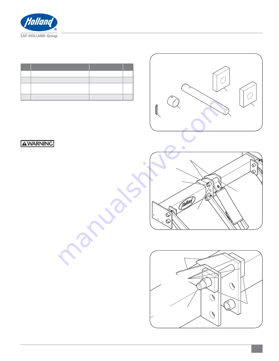
Kits Contents
(Figure 2)
ITEM DESCRIPTION
PART NUMBER
QTY.
1
Lift Frame Boss
2112100004580
2
2
Sleeve, 1-5/16" O.D. x 1" Long
XA-50194
1
3
Hydraulic Cylinder Mounting Pin,
1" Diameter x 8-1/2" Long
XA-50020
1
4
Pin, Spring 1/4" x 1-1/2", Plated
XB-21-S-250-1500P
1
4. Bushing Installation
1. Open and lower the liftgate to the ground in accordance
with the TL and TG Series Operation and Maintenance
Manual XL-TG10150UD-en-US. Avoid contact with electrical
connections inside the pump box which are not isolated.
Failure to avoid contact with electrical
connections will result in shock which,
if not avoided, could result in death or
serious injury.
2. Disconnect the power to the motor.
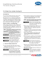
3. With a punch, remove the spring pin from the hydraulic
cylinder mounting pin
(Figure 3)
.
4. Remove the pin and rotate the hydraulic cylinder clevis
out of the mounts
(Figure 3)
.
5. With a grinder, remove the sleeve from the cylinder
mount
(Figure 3)
.
6. Align the new parts. Insert the new pin through one lift
frame boss, both cylinder mount plates and then through
the second lift frame boss
(Figure 4)
.
7. Prep the cylinder mount surfaces where the lift frame
bosses will be welded. With a grinder, remove any paint
or galvanizing within 1" to 4" (25-101 mm) of the weld
surface. Position the lift frame bosses and align the top
and leading edge of the lift frame bosses flush with the
top and leading edge of the cylinder mounts
(Figure 4)
.
Bushing Kit
Part Number: 2074300000090
1
1
2
4
3
Figure 4
Figure 3
CYLINDER MOUNTS
CYLINDER MOUNTS
TOP AND LEADING
EDGE FLUSH
HYDRAULIC
CYLINDER
CLEVIS
LIFT
FRAME
BOSS
SPRING PIN
HYDRAULIC CYLINDER
MOUNTING PIN
HYDRAULIC CYLINDER
MOUNTING PIN
SLEEVE


