XL-AS20016BM-en-US Rev A · 2015-05-28 · Amendments and Errors Reserved · © SAF-HOLLAND, Inc., SAF-HOLLAND, HOLLAND, SAF,
and logos are trademarks of SAF-HOLLAND S.A., SAF-HOLLAND GmbH, and SAF-HOLLAND, Inc.
Installation Instructions
10
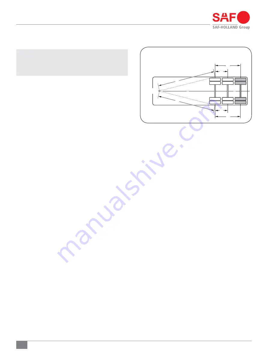
Figure 15
7. SwingAlign
™
Axle Alignment
IMPORTANT:
Axle alignment can only be achieved if the
lockpin holes are the same distance from the
kingpin, left and right. Axle alignment should
always be done while the trailer is empty.
7.1 Alignment Preparation
1. Pull the trailer in a straight line for a sufficient distance
to ensure there are no binds in the suspension.
2. Lock the trailer brakes and pull the trailer straight forward
so the locking pins rest against the rear of the holes in
the body rails.
3. Disengage the trailer parking brakes and ensure the
trailer is empty.
4. Manually measure or use an optical device specifically
designed for alignment measuring to determine the following:
Measure the distance from the king pin to
the centerline of the front axle spindles. It is
recommended that spindle extensions be utilized.
Dimensions A and B
(Figure 15)
MUST be equal to
within 1/8" (3 mm).
Measure the distance from the centerline of the front
axle spindles to the centerline of the rear axle
spindles.
Dimensions C and D, E and F
(Figure 15)
MUST be
equal to within 1/16" (1.5 mm).
For trailers equipped with CBX 69, dimensions E and F
(Figure 15)
MUST be equal to within 1/16" (1.5 mm).
A
B
E
F
D
C
KINGPIN
A=B ± 1/8
"
C=D ± 1/16
"
E=F ± 1/16
"


