


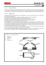


T3385
FLASH
EPLD
DBG1
DBG2
3.3 Volt
DBG0
VCC
ERROR
STATUS
ERROR
CONFIG.
ERROR
1
2
7
6
3
4
5
004AZ011B
FEATURES
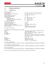
2
2-5
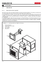
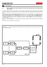
FIGURE 2.1.1.3 - PCI S32P I/O BOARD
1
Mini DIN8-Triggers connector
2
Opto type DSUB37 output/input connector
3
Status leds
4
Auxiliary signal connectors
5
EPLD Acex (programmable logic)
6
Flash
7
Board programming connector
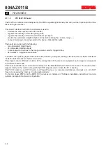
Leds
DGB0
,
DGB1
and
DGB2
depend on the logic.
DGB1
indicates the state of the optoisolated inputs.
3.3 Volt
indicates that board is inserted in a 3.3 V BUS.
VCC ERROR
illuminated signals board 3.3 V power supply failure.
STATUS ERROR
and/or
CONFIG. ERROR
light up only in the event of incorrect (or no) programming.
Summary of Contents for CVS Series
Page 2: ......
Page 4: ...004AZ011B...
Page 8: ...004AZ011B TABLE OF CONTENTS Page 0 8...
Page 16: ...004AZ011B 1 GENERAL INFORMATION 1 8...
Page 37: ...T6912 SAFETY EQUIPMENT AND PRECAUTIONS 3 3 3 004AZ011B FIGURE 3 1 2 LOCKOUT TAGOUT QS1...
Page 46: ...3 SAFETY EQUIPMENT AND PRECAUTIONS 3 12 004AZ011B...
Page 62: ...7 ADJUSTMENTS 7 4 004AZ011B...
Page 66: ...8 MAINTENANCE 8 4 004AZ011B...


