28
Sabine Smart Spectrum
®
Wireless
© 2011 Sabine
, Inc.
FBX Feedback Exterminator
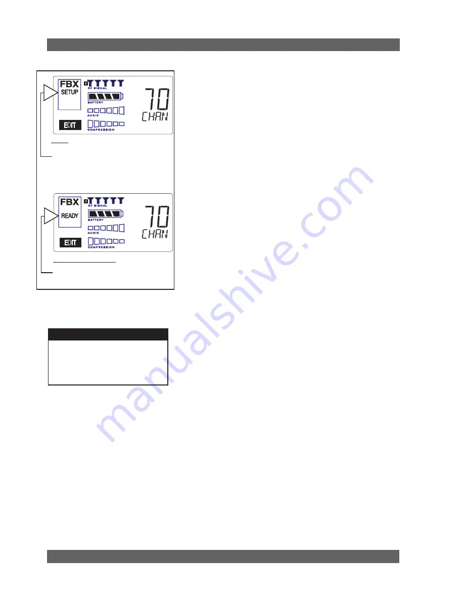
FBX SETuP noTE
LCD “READy” Flashing
As you get close to the end of the setup
procedure, READY will begin to flash on
the LCD.
Stop raising the gain!
The FBX
will now go into Ready Mode.
7. FBX FEEDBACk EXTERMInAToR®
SETUP Indicator
Fig. 7a
Fig. 7b: READY Indicator
NOTE: make sure READY is displayed before
using your system for a performance.
7.1. FBX Introduction
There are two types of FBX filters, fixed and dynamic. Both operate automati-
cally. There is no audible difference between fixed and dynamic filters in terms
of sonic purity; the difference arises in their application.
7.1.1. FBX Fixed Filters
Fixed filters are set automatically during the FBX SETUP and will not change
frequency until manually reset.
7.1.2. FBX Dynamic Filters
Dynamic FBX filters also set automatically, but can change frequency, on a
rotating basis, as the need arises.
7.1.3. Balancing Fixed & Dynamic Filters
Each channel of your receiver offers a total of 10 FBX filters (combined fixed
and dynamic), which can be used as needed to exterminate feedback. The
default setting of 7 Fixed and 3 Dynamic can be changed to 8 Fixed and 2
Dynamic using the DIP switches on the back of your receiver (see Appendix
D FBX Configuration DIP Switch), or to any configuration using the Remote
Control software (see Section 13).
If you follow setup instructions for setting FBX filters, your receiver will auto-
matically exit SETUP mode (enter READY status) after all Fixed filters, and
the first Dynamic filter, have set. In the default condition, this means you
will have set eight filters (seven Fixed and one Dynamic), with two Dynamic
filters still unset and remaining on standby alert. If you wish to set fewer
filters, press the READY button before SETUP automatically exits, after you
have set enough filters to safely achieve your desired gain level. In that
case, in the factory default condition, you will reserve three unset Dynamic
filters for standby.
7.1.4. FBX Filter Width
Sabine’s experience and testing with filters and sound quality along led us to
decide upon a default FBX filter width of .10 (one-tenth) octave as the optimal
notch width, able to eliminate feedback without affecting music programs.
If, with all filters properly set, feedback is still a problem, FBX filters may be
set to .20 (one-fifth) octave width. This wider filter setting will help to better
eliminate feedback trouble areas, but may also affect music programs slightly.
Therefore, the wider setting is generally considered to be appropriate where
speech (less demanding than music) is the primary application of the Sabine
Wireless system. You can globally change FBX filter width by repositioning
a rear panel DIP switch, to change from .10 to .20 octave (see Appendix D
FBX Configuration DIP Switch), or by adjusting filter width using the True
Mobility
®
Remote Software (which allows a range of widths from .01 to 1.0
octave). You may also mix filter widths, either by adjusting individual filter
widths using the Remote Software, or by changing the DIP switch position
during setup. The width of any set filter will always be determined by the
position of the switch at the time the filter is created.
7.2. FBX Set up
Follow these easy steps to obtain the maximum gain and protection from
feedback. Sabine FBX employs a very fast and quiet setup mode to make it
easy to use.
1. Place the speakers in the positions where they will be used during the
program.
2. If there is any equipment with a noise gate in the signal path, you MUST
DISENGAGE the noise gate(s) prior to the setup procedure. You may
reengage these noise gates upon conclusion of your FBX setup.
3. Patch your Sabine receiver into the mixer or amp channel. Set the amp
master output gain to a normal operating position.
NOTE: The level of your power amplifier should be set to a level that allows
a healthy gain structure prior to the amplifier. If your amplifier is turned up
Summary of Contents for SWM6000
Page 2: ......


