background image

11

Chapter 3

Parameter Setting and State Display

3.1

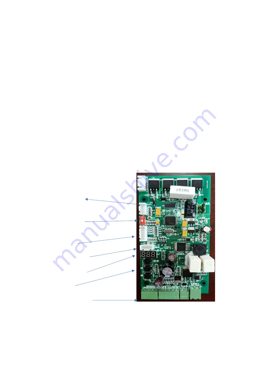
Circuit Board Diagram

The CNC board for door opener uses 3-bit LED digital

tube to display and three keys to set parameters. The

dial switch is used to select the right and left switches.

Jumper selection door opening control signal input is

relay or voltage mode. Check each indicator indicating

the power supply

normally and the Hall state of

speed measurement.

As follows:

Motor terminal

Left & right door

opening selection

Encoder signal

Remote control
Digital display
The keys
External terminal

Summary of Contents for RS-140

Page 1: ...eter Setting Setting Setting Setting and and and and State State State State Display Display Display Display 11 11 11 11 3 1 3 1 3 1 3 1 Parameter Parameter Parameter Parameter Setting Setting Setting...

Page 2: ...ons carefully before you install and use it 1 1Workflow A MainProcess openthedoor open slowdown keepinplace closethe door close slowdown lockthedoor B DetailedWorkflow Step1 The open signal from exter...

Page 3: ...50 d B 3 Small size easy installation 4 Powerful maximum push door weight 140 Kg 5 Support multiple signal input relay signal voltage signal 5 24V 6 motor over current overload short circuit protecti...

Page 4: ...ting Temperature 20 60 Operating Humidity 30 95 no condensation Atmospheric Pressure 700hPa 1060hPa External Size Long 360mm Wide 83mm High 131mm Net Weight about 7 3kg Three Guarantee Period One year...

Page 5: ...roperly and damage the equipment in serious cases C During installation it is forbidden to change the structure of the door opener and no holes can be made in the shell to avoid water and air entering...

Page 6: ...into the main shaft of the door opener Remember to make the position of the keyway on the hole aligned with the key of the main shaft next lock the crank with gasket and screw F Fix the L type mountin...

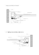
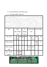
Page 7: ...7 down plane will be forced and blocked 2 1 2 Left open door installation method and size As follows 2 1 3 Right open door installation method and size As follows...

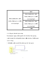
Page 8: ...l operation or circuit damage B When leaving factory the motor wire has been connected do not take it out without any special case C Opening signal of external access control equipment a When the acce...

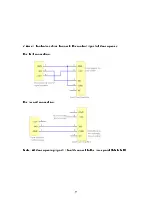
Page 9: ...pen type Infrared photoelectric switch interface Note please use NPN normal open type 12VDC 2 2 2 Diagram of control signal wiring Connect power supply electromagnetic lock and external door opening c...

Page 10: ...10 2 Access Control machine Connects the control signal of door opener the first connection the second connection Note All door opening signals should connect to the same point GNG NO...

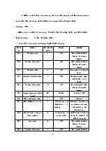
Page 11: ...ers The dial switch is used to select the right and left switches Jumper selection door opening control signal input is relay or voltage mode Check each indicator indicating the power supply normally...

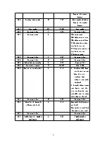
Page 12: ...er larger the the the the angle angle angle angle larger larger larger larger P06 P06 P06 P06 Current Current Current Current Detection Detection Detection Detection High High High High Speed Speed Sp...

Page 13: ...Low speed Low speed Low speed current current current current 35 35 35 35 20 150 20 150 20 150 20 150 Unit Unit Unit Unit 0 01A 0 01A 0 01A 0 01A P22 P22 P22 P22 Remote Remote Remote Remote mode mode...

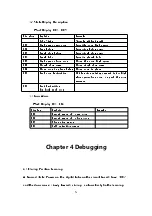
Page 14: ...e door door door door in in in in place place place place Delay Delay Delay Delay Close Close Close Close door door door door in in in in place place place place H08 H08 H08 H08 Push door Push door Pu...

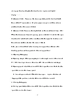
Page 15: ...er it enters the normal state A Note please do not block when learning closing position otherwise the blocking position will be regarded as the closing position 4 2 Opening Debugging A Opening Angle i...

Page 16: ...tube tube tube tube do do do do not not not not light light light light Use Use Use Use a a a a multimeter multimeter multimeter multimeter to to to to Check Check Check Check whether whether whether...

Page 17: ...current current current current low speed low speed low speed low speed torque torque torque torque or or or or increase increase increase increase the the the the value value value value of of of of...

Page 18: ...L type L type L type L type mounting mounting mounting mounting seat seat seat seat 3 3 3 3 Installation Installation Installation Installation screw screw screw screw bag bag bag bag 1 1 1 1 2 2 2 2...

Reviews: