background image

13

RHEASGARD

®

  KLGF 1  ⁄  KLGF 2

ATTENTION!
Trained specialist personnel must execute connection and putting in operation! Mains connection (L, N) is to be made via fused breaker 
switch with the usual cutout elements. Electric installation must on principle follow the general VDE directives (VDE 0100, VDE 0113, 
VDE 0160).   

Putting  in  operation  –  KLGF 1 ⁄  2

Specialist personnel must execute connection and putting in operation! 
For putting in operation and calibrating the devices, the following procedure is practical: 

•  Install flow monitor and make electrical connections according to mounting and installation instructions.
• Switch on mains voltage, then turn on nominal flow. 
• At the KLGF 1  

   2, calibrate the respective output signal to the nominal flow using the »Amplification« potentiometer. For example,       

for nominal flow 5 m  ⁄  s, calibrate signal output U to 5 V, for nominal flow 10 m  ⁄  s, calibrate signal output U to 10 V

• The flow meter is now operable. 

The device is now set to monitoring function.

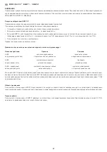
 What to do when air flow monitor doesn‘t function 

Problem  

Cause   

Solution

KLGF... doesn‘t  

No or incorrect 

Check 

function at all  

mains voltage connected 

mains voltage and connection 

KLGF... doesn‘t  

Sensor is not  

Check  

recognize flow  

installed correctly  

mounting conditions 

KLGF... shows changed 

Sensor is highly contaminated  

Clean Sensor  

responding behaviour  

by the medium  

carefully with water

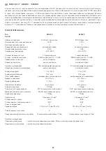
In the KLGF 1 ⁄ 2, sensor and control device form one compact unit. The sensor tube is also used for mounting. With KLGF 1 ⁄ 2, the rela-
tive intensity of flows can be indicated and evaluated. At the device, you can adapt the analog output range to the existing flow conditions 
by setting the desired output voltage (max.10 V) at maximum flow. 

Intended use 
Series KLGF 1 ⁄ 2 flow monitors are used for monitoring flow rates in gaseous media within specified technical data limits. Main fields of 
application are air conditioning and ventilation technology in sectors of building and facility automation.  

Mode of operation 
Series KLGF 1 ⁄ 2 flow monitors function on the calorimetric principle and provide a 0...10 V output signal analog to flow velocity. 

Summary of Contents for RHEASREG KLSW-3

Page 1: ...Operating Instructions Mounting Installation Duct airflow monitors including mounting flange electronic one step and two step with active switching output F Notice d instruction Contrôleur de flux d air de gaine y compris bride de montage électronique à un et deux étages avec sortie active tout ou rien r Руководство по монтажу и обслуживанию Реле контроля воздушного потока канальное вкл присоедини...

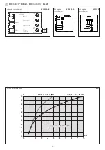
Page 2: ...imensional drawing Plan coté Габаритный чертеж Maßzeichnung MF Dimensional drawing Plan coté Габаритный чертеж KLSW 3 4 5 6 KLGF 2 KLGF 1 mit Display with display avec écran с дисплеем Thor II KLGF 1 mit Display with display avec écran с дисплеем Thor II ...

Page 3: ...spannung führenden Leitungen vermeiden oder abgeschirmte Leitungen verwenden Mindestquerschnitt 1 5 mm2 je Leiter Schirm einseitig auflegen Umgebungstemperatur 0 C 60 C Gerät 0 C 80 C Medium Fühler Fühlerbruchsicherung temperaturkompensiert Gehäuse Kunststoff Werkstoff Polyamid 30 glaskugelverstärkt Farbe reinweiß ähnlich RAL 9010 Abmaße Gehäuse KLSW xx KLGF 2 KLGF 1 mit Display 108 x 70 x 73 5 mm...

Page 4: ... m s 10 V Ausgang 10 m s 10 V Ausgang Temperatur Luftstrom 20 C Schaltbild KLSW 5 6 Anschlussbild KLGF 1 2 Schaltbild KLSW 3 4 Sensor 1 2 3 4 5 6 7 8 11 10 9 min BN BK BU max L N 15s 120s 2s 20s 1 10 KLSW 5 6 Hysterese Alarm Strömung Strömungs geschwindigkeit Einschalt verzögerung Ausschalt verzögerung ...

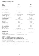
Page 5: ...bar 10 bar Schutzart Gehäuse IP 65 IP 65 Schutzart Sensor IP 67 IP 67 Verschmutzungsklasse II II Anschluss 3 Klemmen 2 5 mm2 3 Klemmen 2 5 mm2 Gehäuseabmessungen ohne Display 72 x 64 x 37 8 mm Thor III 72 x 64 x 37 8 mm Thor III mit Display 108 x 70 x 73 5 mm Thor II Prüfzeichen 0 0 Zubehör Montageflansch Montageflansch Referenzbedingungen Einlaufstrecke 10 x DN Auslaufstrecke 5 x DN laminare Strö...

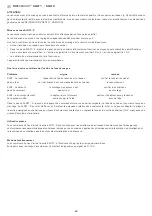
Page 6: ...em Ursache Lösung KLGF funktioniert Keine oder falsche Netzspannung und Anschluss überhaupt nicht Netzspannung angeschlossen überprüfen KLGF erkennt Sensor ist nicht richtig Einbaubedingungen Strömung nicht installiert überprüfen KLGF hat verändertes Sensor ist durch das Medium Sensor vorsichtig mit Wasser Ansprechverhalten stark verschmutzt reinigen Bei dem KLGF 1 2 bilden Fühler und Steuergerät ...

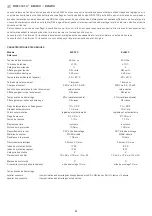
Page 7: ... Überspannungskategorie II II Signalanzeige Spannung Grüne LED Grüne LED Leistungsaufnahme max 2 VA 4 VA Umgebungstemperatur Gerät 20 60 C 20 60 C Signalausgang Strömung 1 Wechsler 1 Wechsler Strom Kontaktbelastbarkeit 250 VAC 6 A 1 5 kVA 250 VAC 6 A 1 5 kVA Schaltfunktion bei Strömung Relais zieht an Relais zieht an Signalanzeige bei Strömung Gelbe LED Gelbe LED Anlaufüberbrückung 60 s Jumper akt...

Page 8: ...chkeit des Gerätes erforderliche Strömung erst nach beendetem Hochlauf vorhanden ist Während der Hochlaufzeit könnte das Strömungsüberwachungsgerät auf Störung schalten Bei dem KLSW 6 ist eine einstellbare 2 120 Sek Anlaufüberbrückung integriert welches die Anlaufphase überbrückt Während dieser Zeit zieht das Ausgangsrelais Strömung an die rote LED Luftstrom leuchtet Das Gerät verhält sich dadurch...

Page 9: ...ung ausgeschlossen Die Installation der Geräte darf nur durch Fachpersonal erfolgen Es gelten ausschließlich die technischen Daten und Anschlussbedingungen der zum Gerät gelieferten Montage und Bedienungs anleitung Abweichungen zur Katalogdarstellung sind nicht zusätzlich aufgeführt und im Sinne des technischen Fortschritts und der stetigen Verbesserung unserer Produkte möglich Bei Veränderungen d...

Page 10: ...use shielded cables minimum cross section1 5 mm2 per conductor apply cable screen one sided Ambient temperature 0 C 60 C at the device 0 C 80 C medium Sensor sensor breakage protection temperature compensated Enclosure plastic material polyamide 30 glass globe reinforced colour pure white similar RAL 9010 Enclosure dimensions KLSW xx KLGF 2 KLGF 1 with display 108 x 70 x 73 5 mm Thor II KLGF 1 wit...

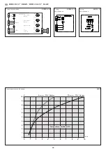
Page 11: ...ASGARD KLGF Schematic diagram KLSW 5 6 Connecting KLGF 1 2 diagram Schematic KLSW 3 4 diagram Sensor 1 2 3 4 5 6 7 8 11 10 9 min BN BK BU max L N 15s 120s 2s 20s 1 10 KLSW 5 6 Hysteresis Alarm Flow Flow velocity Switch on delay Switch off delay ...

Page 12: ...ted Pressure resistance 10 bar 10 bar Protection type enclosure IP 65 IP 65 Protection type sensor IP 67 IP 67 Contamination class II II Connection 3 terminals 2 5 mm2 3 terminals 2 5 mm2 Enclosure dimensions without display 72 x 64 x 37 8 mm Thor III 72 x 64 x 37 8 mm Thor III with display 108 x 70 x 73 5 mm Thor II Test mark 0 0 Accessories mounting flange mounting flange Reference conditions In...

Page 13: ... set to monitoring function What to do when air flow monitor doesn t function Problem Cause Solution KLGF doesn t No or incorrect Check function at all mains voltage connected mains voltage and connection KLGF doesn t Sensor is not Check recognize flow installed correctly mounting conditions KLGF shows changed Sensor is highly contaminated Clean Sensor responding behaviour by the medium carefully ...

Page 14: ...max 2 VA 4 VA Device ambient temperature 20 60 C 20 60 C Signal output flow 1 changeover contact 1 changeover contact Current contact load 250 V AC 6 A 1 5 kVA 250 V AC 6 A 1 5 kVA Switching function at flow relay activated relay activated Signal indication at flow yellow LED yellow LED Start bridging 60 s via jumper 60 s via jumper Start bridging indication yellow LED yellow LED Media temperature...

Page 15: ...un up the flow monitor could switch to failure On the KLSW 6 adjustable start bridging 2 120 s is integrated bridging the start up phase During this period output relay Flow is activated the red LED Air flow lights up Thereby the device acts as if flow would exist so that switch off is avoided We recommend to switch on devices with start bridging together with the flow generator as bridging time i...

Page 16: ...ty or liability These devices must be installed by authorised specialists only The technical data and connecting conditions of the mounting and operating instructions delivered together with the device are exclusively valid Deviations from the catalogue representation are not explicitly mentioned and are possible in terms of technical progress and continuous improvement of our products In case of ...

Page 17: ...t env 2 20 s réglable Longueur de câble de la sonde max 50 m ne pas poser les câbles de sonde en parallèle avec des câbles secteur ou utiliser des câbles blindés section minimum 1 5 mm2 par fil blindage à placer d un seul côté Température ambiante 0 C 60 C appareil 0 C 80 C milieu Sonde protection contre rupture de sonde compensation de température Boîtier matière plastique polyamide renforcé à 30...

Page 18: ...GARD KLGF Schéma de raccordement KLSW 5 6 Schéma de KLGF 1 2 raccordement Schéma de KLSW 3 4 raccordement Sensor 1 2 3 4 5 6 7 8 11 10 9 min BN BK BU max L N 15s 120s 2s 20s 1 10 KLSW 5 6 Hysteresis Alarm Flow Flow velocity Switch on delay Switch off delay ...

Page 19: ... 65 IP 65 Indice de protection capteur IP 67 IP 67 Catégorie de pollution II II Raccordement électrique 3 bornes 2 5 mm2 3 bornes 2 5 mm2 Dimensions du boîtier sans écran 72 x 64 x 37 8 mm Thor III 72 x 64 x 37 8 mm Thor III avec écran 108 x 70 x 73 5 mm Thor II Marque de conformité 0 0 Accessoires bride de montage bride de montage Conditions de référence Longueur en amont 10 x DN longueur en aval...

Page 20: ... pas branché sur le réseau vérifier la tension réseau et pas du tout ou il est branché sur une mauvaise tension réseau le raccordement KLGF ne détecte le montage du capteur n est vérifier les conditions pas d écoulement pas correct de montage KLGF a un comportement le capteur a été fortement nettoyer le capteur avec précaution de réponse modifié encrassé par le fluide avec de l eau Dans le cas du ...

Page 21: ...ommation électrique 2 VA maxi 4 VA maxi Température ambiante de l appareil 20 60 C 20 60 C Sortie de signal écoulement 1 inverseur 1 inverseur Charge par contact 250 V ca 6 A 1 5 kVA 250 V ca 6 A 1 5 kVA Fonction de commutation lors de l écoulement relais s active relais s active Affichage signal lors de l écoulement DEL jaune DEL jaune Temporisation au démarrage 60 s cavalier activable 60 s caval...

Page 22: ...L appareil de contrôle du flux d air pourrait passer en mode perturbation pendant le temps de démarrage Les appareils du type KLSW 6 intègrent une temporisation au démarrage réglable 2 120 s qui sert à franchir la phase de démarrage Pendant ce temps le relais sortie écoulement s active la DEL rouge flux d air s allume Ainsi l appareil se comporte comme s il y avait un écoulement ce qui empêche que...

Page 23: ... L installation des appareils doit être effectuée uniquement par un spécialiste qualifié Seules les données techniques et les conditions de raccordement indiquées sur la notice d instruction accompagnant l appareil sont applicables des différences par rapport à la présentation dans le catalogue ne sont pas mentionnées explicitement et sont possibles suite au progrès technique et à l amélioration c...

Page 24: ...оводке подводящей питающее напряжение либо использовать экранированные кабели минимальное поперечное сечение каждого провода 1 5 мм2 экранировать с одной стороны Температура окружающей среды 0 C 60 C прибор 0 C 80 C среда Датчик защита от выхода из строя датчика с температурной компенсацией Корпус пластик полиамид 30 усиление стеклянными шариками цвет чистый белый аналогичен RAL 9010 Размеры корпу...

Page 25: ...SW RHEASGARD KLGF Схема подключения KLSW 5 6 Схема KLGF 1 2 подключения Схема KLSW 3 4 подключения Sensor 1 2 3 4 5 6 7 8 11 10 9 min BN BK BU max L N 15s 120s 2s 20s 1 10 KLSW 5 6 Hysteresis Alarm Flow Flow velocity Switch on delay Switch off delay ...

Page 26: ...унь Предельное давление 10 бар 10 бар Степень защиты корпус IP 65 IP 65 Степень защиты чувствительный эл т IP 67 IP 67 Класс по загрязнению II II Подключение 3 зажима 2 5 мм2 3 зажима 2 5 мм2 Размеры корпуса без дисплея 72 x 64 x 37 8мм Thor III 72 x 64 x 37 8мм Thor III с дисплеем 108 x 70 x 73 5 мм Thor II Знак технического контроля 0 0 Принадлежности присоединительный фланец присоединительный ф...

Page 27: ...ина Решение KLGF сетевое напряжение не проверить сетевое не функционирует вообщ подключено или неправильное напряжение и подключение KLGF чувствительный элемент проверить не распознает поток установлен неверно условия монтажа KLGF срабатывает чувствительный элемент сильно чувствительный элемент иначе чем требуется загрязнен средой осторожно промыть водой В случае KLGF1 2 датчик и устройство управл...

Page 28: ...температура 20 60 C 20 60 C Сигнальный выход поток 1 переключающий 1 переключающий Токовая контактная нагрузка 250 В перем тока 6 A 1 5 кВА 250 В перем тока 6 A 1 5 кВА Срабатывание при потоке реле втягивается реле втягивается Индикация при потоке желтый светодиод желтый светодиод Пусковое шунтирование 60 с активируемая перемычка 60 с активируемая перемычка Индикация пускового шунтирования желтый ...

Page 29: ...дусмотрено настраиваемое 2 120 с пусковое шунтирование за счет чего возможно избежание ложных срабатываний в процессе пуска В течение этого времени выходное реле поток втянуто красный светодиод воздушный поток горит Прибор ведет себя так как при наличии достаточного воздушного потока его отключение не происходит Мы рекомендуем включать приборы с пусковым шунтированием совместно с устройствами созд...

Page 30: ...ществляться только квалифицированным персоналом Действительны исключительно технические данные и условия подключения приведенные в поставляемых с приборами руководствах по монтажу и эксплуатации Отклонения от представленных в каталоге характеристик дополнительно не указываются несмотря на их возможность в силу технического прогресса и постоянного совершенствования нашей продукции В случае модифика...

Page 31: ... Copyright by S S Regeltechnik GmbH Nachdruck auch auszugsweise nur mit Genehmigung von S S Regeltechnik GmbH gestattet Reprints in part or in total are only permitted with the approval of S S Regeltechnik GmbH La reproduction des textes même partielle est uniquement autorisée après accord de la société S S Regeltechnik GmbH Перепечатка в том числе в сокращенном виде разрешается лишь с согласия S ...

Page 32: ...ж Maßzeichnung MF Dimensional drawing Plan coté Габаритный чертеж KLGF 1 ohne Display kompakt without display compact sans écran compact без дисплея компактное исполнение Thor III KLGF 1 ohne Display without display sans écran без дисплея Thor III 64 107 140 72 14 8 10 ø10 37 8 M16x1 5 ...

Reviews: