background image

11

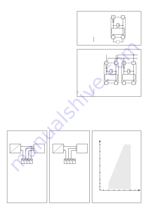
Load resistance diagram 

AFF - xx - I 

4...  20 mA 

AFTF - xx - I 

800

700

600

500

400

300
250

50

200

10

15

20

25

30 35 36 40

Load resistance diagram

W

orking r

esis

tanc

e  (Ohm)

Operating voltage  (V DC)

Admissible

  range

800

700

600

500

400

300
250

50

200

10

15

20

25

30 35 36 40

Load resistance diagram

W

orking r

esis

tanc

e  (Ohm)

Operating voltage  (V DC)

Admissible

  range

NOTE

For 4...20 mA devices, DC voltage must be used  
(without residual  ripple, see permissible range of load 
resistance diagram). Do not use pulsating DC voltage.

Connecting diagram 

AFTF - xx -U 

Output: 


with  ⁄ without


0 -10 V


Display

Connecting diagram 

AFTF - xx - I  

Output: 


with  ⁄ without


4...20  mA 

Display

NOTE

At transmitters with current output the humidity output (Pin 2)  
must categorically be connected !

1 2 3 4

230V AC

24V AC/DC

PLC

PC

+U

24

AC

/D

C

O

ut

pu

t h

um

id

ity 

in 

r.H

. 0

-1

0V

O

ut

pu

t t

em

pe

ra

tu

re 

in 

°C 

0-

10

V

–UB

-GN

D

1 2 3 4

230V AC

24V DC

+U

24

D

C

O

ut

pu

t h

um

id

ity 

in 

r.H

. 4

...

20m

A

O

utp

ut

 tem

per

at

ur

in

 °

C

 4

...

20m

A

PLC

Working

resistance

–UB  GND  (optional f

or

LCD back

gr

ound lightling)

Connecting scheme 

Parallel operation

Connecting scheme 

Individual operation

SUPPLY VOLTAGE:

For operating voltage reverse polarity protection, a one-way rectifier or 
reverse polarity protection diode is integrated in this device variant. 


This internal one-way rectifier also allows operating 0 - 10 V devices on AC 
supply voltage.

The output signal is to be tapped by a measuring instrument. Output  
voltage is measured against zero potential (O V) of the input voltage!

When this device is operated on 

DC supply voltage

, the operating voltage 

input UB+ is to be used for 15...36 V DC supply and UB – or GND for ground 
wire!

When several devices are supplied by one 24 V

 AC voltage supply

, it is to 

be ensured that all ”positive“ operating voltage input terminals (+) of the 
field devices are connected with each other and all ”negative“ operating 
voltage input terminals (–) (= reference  potential) are connected together 
(in-phase connection of field devices). All outputs of field devices must be 
referenced to the same potential!

In case of reversed polarity at one field device, a supply voltage short- 
circuit would be caused by that device. The consequential short-circuit 
current flowing through this field device may cause damage to it.

Therefore, pay attention to correct wiring!

Circuitry

Circuitry

0...10V

0V/GND

0...10V

0V/GND

Power supply

AC 24V~ 

0V

DC 15-36V =  GND

Circuitry

0...10V

0V/GND

V

Power supply

AC 24V~ 

0V

DC 15-36V =  GND

HYGRASGARD

®

  AFTF - 20 - VA

Summary of Contents for HYDRASGARD AFTF-20-VA ID Series

Page 1: ...ure sensors 1 8 calibratable with multi range switching and active output F Notice d instruction Sonde d humidit et de temp rature 1 8 pour montage en saillie talonnable avec commutation multi gamme e...

Page 2: ...143 61 126 8 8 17 126 8 8 17 Geh use mit M12 Steckverbinder Housing with M12 connector Bo tier avec connecteur M12 M12 Geh use mit Kabelverschraubung Housing with cable gland Bo tier avec presse toupe...

Page 3: ...erende Luft Abweichung Feuchte typisch 1 8 10 90 r H bei 25 C sonst 2 0 Ausgang Feuchte 0 10 V bei U Variante 4 20 mA bei I Variante TEMPERATUR Messbereich Temperatur Mehrbereichsumschaltung siehe Tab...

Page 4: ...0 8 8 20 4 0 10 4 25 5 0 12 0 30 6 0 13 6 35 7 0 15 2 40 8 0 16 8 45 9 0 18 4 50 10 0 20 0 HYGRASGARD AFTF 20 VA Aufputz Feuchte und Temperaturf hler 1 8 ID HYGRASGARD AFTF 20 VAQ Aufputz Feuchte und...

Page 5: ...undbeleuchtung Shield 3 Leiter Anschluss f r Ger te ohne mit Display unbeleuchtet 4 Leiter Anschluss f r Ger te mit beleuchtetem Display Bei der I Variante ist der Feuchte pfad zwingend anzuschlie en...

Page 6: ...de integriert Diese interne Einweggleichrichtung erlaubt auch den Betrieb mit AC Versorgungs spannung bei 0 10 V Ger ten Das Ausgangssignal ist mit einem Messger t abzugreifen Hierbei wird die Ausgang...

Page 7: ...Dieses Ger t ist nur f r den angegebenen Verwendungszweck zu nutzen dabei sind die entsprechenden Sicherheitsvorschriften des VDE der L nder ihrer berwachungsorgane des T V und der rtlichen EVU zu bea...

Page 8: ...Deviation in humidity typically 1 8 10 90 r H at 25 C otherwise 2 0 Output humidity 0 10 V for U variant 4 20 mA for I variant TEMPERATURE Measuring range temperature multi range switching see table...

Page 9: ...12 0 30 6 0 13 6 35 7 0 15 2 40 8 0 16 8 45 9 0 18 4 50 10 0 20 0 ACCESSORIES SF M Metal sinter filter 16 mm L 32 mm exchangeable stainless steel V4A 1 4404 7000 0050 2200 100 WS 01 Sun and ball impa...

Page 10: ...ut temperature 4 20mA in C UB GND optional for LCD backlighting 3 wire connection for devices with without display not illuminated 4 wire connection for devices with illuminated display At the I varia...

Page 11: ...tage reverse polarity protection a one way rectifier or reverse polarity protection diode is integrated in this device variant This internal one way rectifier also allows operating 0 10 V devices on A...

Page 12: ...ed and EMC directives are to be observed This device shall only be used for its intended purpose Respective safety regulations issued by the VDE the states their control authorities the T V and the lo...

Page 13: ...t humidit typique 1 8 10 90 h r 25 C sinon 2 0 Sortie humidit 0 10 V pour variante U 4 20 mA pour variante I TEMP RATURE Plage de mesure temp rature commutation multi gamme voir tableau 35 35 C 35 75...

Page 14: ...0 30 6 0 13 6 35 7 0 15 2 40 8 0 16 8 45 9 0 18 4 50 10 0 20 0 ACCESSOIRES SF M filtre fritt en m tal 16 mm L 32 mm rempla able en acier inox V4A 1 4404 7000 0050 2200 100 WS 01 protection contre le s...

Page 15: ...N 0 80 C O N OFF Affectation des plots de connexion M12 Affectation des plots de connexion M12 AFTF xx U AFTF xx I 1 2 3 4 5 45 1 2 3 4 5 UB 24V AC DC Output humidity 0 10V r H Output temperature 0 1...

Page 16: ...re l inversion de polarit c d elle comprend un redressement demi onde diode de redressement Gr ce cette diode de redressement int gr e les appareils 0 10 V peuvent galement tre aliment s en courant al...

Page 17: ...ll le avec des c bles de puissance les directives CEM sont respecter Cet appareil ne doit tre utilis que pour l usage qui est indiqu en respectant les r gles de s curit correspondantes de la VDE des L...

Page 18: ...2 2 24 0 100 95 1 8 10 90 25 C 2 0 0 10 B U 4 20 I 35 35 C 35 75 C 0 50 C 0 80 C 35 85 C 30 80 C 0 2 K 25 C 0 10 B U 4 20 I 0 14 1 5 V2A 1 4305 M 20 x 1 5 6 12 M12 5 A DIN EN 61076 2 101 V4A 1 4571 14...

Page 19: ...0 0 7 5 1 25 1 4 6 3 20 2 1 7 4 15 2 9 8 6 10 3 6 9 7 5 4 3 10 9 0 5 0 12 0 5 5 7 13 1 10 6 4 14 3 15 7 1 15 4 20 7 9 16 6 25 8 6 17 7 30 9 3 18 9 35 10 0 20 0 0 50 C C UA B IA A 0 0 0 4 0 5 1 0 5 6 1...

Page 20: ...perature 4 20mA C UB GND optional for LCD backlighting Shield 3 4 I DIP 1 DIP 2 35 75 C O N O N 35 35 C OFF OFF 0 50 C default OFF O N 0 80 C O N OFF 1 2 3 4 1 2 3 4 5 6 ON DIP C offset r H Plug for d...

Page 21: ...range 4 20 AFTF xx U 0 10 AFTF xx I 4 20 A 2 1 2 3 4 230V AC 24VAC DC PLC PC UB 24V AC DC Output humidity in r H 0 10V Output temperature in C 0 10V UB GND 1 2 3 4 230V AC 24V DC UB 24V DC Output humi...

Page 22: ...22 r 0 100 0 10 4 20 10 0 99 9 0 10 24 ZVEI VDE EMV...

Page 23: ...ol their particular suitability must be verified by each customer and or end user themselves Existing property rights must be observed We warrant the faultless quality of our products as stated in our...

Page 24: ...24 HYGRASGARD AFTF 20 VA D G F r AFTF 20 VA AFTF 20 VAQ AFTF 20 VA LCD AFTF 20 VAQ LCD...

Reviews: