background image

13

G  

Installation and Commissioning

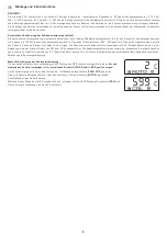
ATTENTION!   

The minimum CO2


concentration of outdoor air amounts to approx. 350  ppm (output voltage = 1.75 V


at  MR = 0...2000  ppm  or  0.7 V  at 

MR = 0...5000  ppm)  in leafy, hardly industrialised areas. Gas inter-exchange in the sensor element happens by diffusion.


Depending on the changes  

to the concentration and the flow velocity of the air surrounding the sensor, the reaction of the device to the change of concentration may take  
place with a delay. It is essential to choose an installation location for the device


in which the air stream flows around the sensor. Otherwise the 

gas exchange may be  considerably delayed or prevented.  

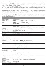
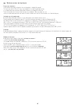
Automatic calibration of the carbon dioxide measurement


(default)

The automatic background logic is a self-calibrating mechanism that is suitable for use in applications in which the CO2 concentration drops to fresh 
air level (350  -  400  ppm) at least three times in 7 days. This should typically occur during times in which rooms are unoccupied. The sensor reaches 
its normal accuracy after 24 hours of continuous operation in an environment that has been subjected to a fresh air supply of 400  ppm CO2. The 
deviation errors remain minimal if the sensor is exposed to fresh air at least 4 times within 21 days. The device needs a permanent operating mode 
without interruptions to the power supply to be able to work correctly.

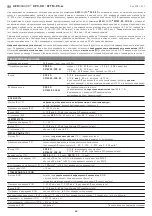
Manual calibration of carbon dioxide measurement

Manual calibration can be carried out independently of the DIP switch position.  

Sufficient fresh air (CO2 content = 500  ppm) must be provided before and after the calibration procedure! 

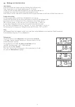
The calibration procedure is started by pressing the “

ZERO  CO2

”  (for approx. five seconds).  

This is signalled by the flashing LED or the countdown timer on the display (

AUTO 0

).  

Then calibration takes place.  
During this phase, the LED is constantly active  and a 600-second countdown runs on the display 

CAL 0

).  

The LED is deactivated after successful calibration.


Summary of Contents for AERASGARD RFTM-PS Series

Page 1: ...ture fine dust PM and CO2 content calibratable with active switching output F Notice d instruction Sonde d ambiance multifonctions resp convertisseur de mesure pour l humidit la temp rature les partic...

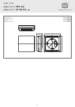
Page 2: ...2 AERASGARD RPS SD AERASGARD RFTM PS xx D G F r Ma zeichnung Geh use Baldur2 Dimensional drawing Housing Baldur2 Plan cot bo tier Baldur2 Baldur2 T K 6 0 98 98 32 6...

Page 3: ...24 V DC 6 4 VA 24 V AC Peakstrom 200 mA Ausgang RPS SD 0 10 V fest eingestellt RFTM PS CO2 W 0 10 V oder 4 20 mA B rde 800 ber DIP Schalter w hlbar gew hlte Variante gilt einheitlich f r alle Ausg ng...

Page 4: ...AERASGARD RPS SD Raumf hler f r Feinstaub PM Standard RFTM PS W Multifunktionaler Raumf hler f r Feuchte Temperatur und Feinstaub PM Premium RFTM PS CO2 W Multifunktionaler Raumf hler f r Feuchte Temp...

Page 5: ...3 default ON OFF 0 300 g m3 OFF ON 0 500 g m3 ON ON Feinstaub PM Partikelgr e DIP 3 PM 2 5 default ON PM 10 OFF CO2 Gehalt DIP 4 0 2000 ppm default OFF 0 5000 ppm ON CO2 Nullpunktautomatik DIP 6 deakt...

Page 6: ...m f llt Dies sollte typischerweise w hrend den Zeiten in denen die R ume nicht belegt sind erfolgen Der Sensor erreicht seine normale Genauigkeit nach 24 Stunden Dauerbetrieb in einer Umgebung die ein...

Page 7: ...00 1900 ppm bei MB 0 2000 ppm bzw 900 4700 ppm bei MB 0 5000 ppm Bei den anderen Mess gr en wird die jeweilige Untergrenze direkt als Basis verwendet PM 10 95 vom Messbereich g m Temperatur 5 48 C Feu...

Page 8: ...ger t abzugreifen Hierbei wird die Ausgangssignal gegen das Nullpotenial O V der Eingangsspannung ge messen Wird dieses Ger t mit DC Versorgungsspannung betrieben ist der Betriebsspannungseingang UB f...

Page 9: ...ie EMV Richtlinien zu beachten Dieses Ger t ist nur f r den angegebenen Verwendungszweck zu nutzen dabei sind die entsprechenden Sicherheitsvorschriften des VDE der L nder ihrer berwachungsorgane des...

Page 10: ...RPS SD 0 10 V fixed RFTM PS CO2 W 0 10 V or 4 20 mA working resistance 800 selectable via DIP switches selected version applies uniformly to all outputs with offset potentiometer 10 of measuring range...

Page 11: ...dust and CO2 content as well as for switch point display AERASGARD RPS SD Room sensor for fine dust PM Standard RFTM PS W Multifunctional room sensor for humidity temperature and fine dust PM Premium...

Page 12: ...3 OFF OFF 0 100 g m3 default ON OFF 0 300 g m3 OFF ON 0 500 g m3 ON ON Fine dust PM Particle size DIP 3 PM 2 5 default ON PM 10 OFF CO2 content DIP 4 0 2000 ppm default OFF 0 5000 ppm ON CO2 automatic...

Page 13: ...l 350 400 ppm at least three times in 7 days This should typically occur during times in which rooms are unoccupied The sensor reaches its normal accuracy after 24 hours of continuous operation in an...

Page 14: ...ppm or 900 4700 ppm with MR 0 5000 ppm With other measurands the corresponding lower limit is used directly as a basis PM 10 95 of measuring range g m Temperature 5 48 C Humidity 10 95 r H The assign...

Page 15: ...reverse polarity protection diode is integrated in this device variant This internal one way rectifier on AC supply voltage The output signal is to be tapped by a measuring instrument The output sign...

Page 16: ...el with current carrying lines is to be avoided and EMC directives are to be observed This device shall only be used for its intended purpose Respective safety regulations issued by the VDE the states...

Page 17: ...V CA RFTM PS CO2 W typique 4 4 W 24 V CC 6 4 VA 24 V CA pointe de courant 200 mA Sortie RPS SD 0 10 V r gl par d faut RFTM PS CO2 W 0 10 V ou 4 20 mA charge 800 s lectionnable via interrupteur DIP la...

Page 18: ...n CO2 et du point de commutation AERASGARD RPS SD Sonde d ambiance pour particules fines PM Standard RFTM PS W Sonde d ambiance multifonctions pour l humidit la temp rature et les particules fines PM...

Page 19: ...g m3 default ON OFF 0 300 g m3 OFF ON 0 500 g m3 ON ON Particules fines PM Taille de particules DIP 3 PM 2 5 default ON PM 10 OFF Teneur en CO2 DIP 4 0 2000 ppm default OFF 0 5000 ppm ON Point z ro au...

Page 20: ...en 7 jours le niveau air frais 350 400 ppm Cela devrait g n ralement avoir lieu dans les p riodes pendant lesquelles les locaux ne sont pas occup s Le capteur atteint sa pr cision normale au bout de 2...

Page 21: ...B 0 5000 ppm Pour les autres grandeurs de mesure la valeur minimale respective est directement utilis e comme valeur de base PM 10 95 de la plage de mesure g m Temp rature 5 48 C Humidit 10 95 h r L a...

Page 22: ...signal de sortie doit tre pr lev avec un appareil de mesure Ce faisant le signal de sortie est mesur e par rapport au potentiel z ro O V de la tension d entr e Si cet appareil est aliment en courant c...

Page 23: ...d s ne pas poser les c bles de sondes en parall le avec des c bles de puissance les directives CEM sont respecter Cet appareil ne doit tre utilis que pour l usage qui est indiqu en respectant les r gl...

Page 24: ...RPS SD 0 10 RFTM PS CO2 W 0 10 4 20 800 DIP 10 RPS SD RFTM PS CO2 W 24 1 A DIP RH C RH 0 100 RH 0 10 B 4 20 DIP RH 2 0 20 80 25 C 3 0 C 0 50 C C 0 10 B 4 20 DIP C 0 2 K 25 C DIP 0 50 0 100 0 300 0 500...

Page 25: ...0 3 W 1501 2116 7301 000 RFTM PS W LCD 0 100 0 50 C 4x W 1501 2116 7321 000 RFTM PS CO2 W RFTM PS CO2 W 0 100 0 50 C 0 50 3 0 100 3 0 300 3 0 500 3 0 2000 1 0 5000 1 W 1501 2113 7301 000 RFTM PS CO2 W...

Page 26: ...OM NO relay switch point humidity r H fine dust g m3 Outputs temperature C DIP RFTM PS xx DIP 1 DIP 2 0 50 3 OFF OFF 0 100 3 default ON OFF 0 300 3 OFF ON 0 500 3 ON ON DIP 3 2 5 default ON 10 OFF CO2...

Page 27: ...27 r CO2 350 1 1 75 0 2000 1 0 7 0 5000 1 automatic background logic CO2 350 400 1 7 24 CO2 400 1 4 21 DIP CO2 500 1 ZERO CO2 AUTO 0 600 CAL 0...

Page 28: ...28 r 30 50 10 95 SET CO2 10 400 1 600 1900 1 0 2000 1 900 4700 1 0 5000 1 10 95 h 3 5 48 C 10 95 DIP DIP 7 DIP 8 10 CO2 ppm 3 C r H C CO2 P T H r H...

Page 29: ...6 85 8 5 17 6 40 4 0 10 4 90 9 0 18 4 45 4 5 11 2 95 9 5 19 2 100 10 0 20 0 0 50 C C UA IA A 0 0 0 4 0 5 1 0 5 6 10 2 0 7 2 15 3 0 8 8 20 4 0 10 4 25 5 0 12 0 30 6 0 13 6 35 7 0 15 2 40 8 0 16 8 45 9...

Page 30: ...30 r VOC 10 95 0 50 C 24 ZVEI VDE EMV...

Page 31: ...wledge at date of publication They are only meant to inform about our products and their application potential but do not imply any warranty as to certain product characteristics Since the devices are...

Page 32: ...32 AERASGARD RPS SD AERASGARD RFTM PS xx D G F r...

Reviews: