15
G
Installation and Commissioning
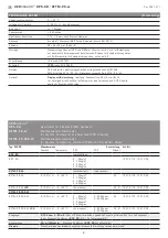
Humidity table
MR: 0...100 % r. H.
%
r.H.
U
A
in V
I
A
in mA
%
r.H.
U
A
in V
I
A
in mA
0
0
4.0
50
5.0
12.0
5
0.5
4.8
55
5.5
12.8
10
1.0
5.6
60
6.0
13.6
15
1.5
6.4
65
6.5
14.4
20
2.0
7.2
70
7.0
15.2
25
2.5
8.0
75
7.5
16.0
30
3.0
8.8
80
8.0
16.8
35
3.5
9.6
85
8.5
17.6
40
4.0
10.4
90
9.0
18.4
45
4.5
11.2
95
9.5
19.2
Continued at the right ...
100
10.0
20.0
Temperature table
MR: 0...+50 °C
°C
U
A
in V
I
A
in mA
0
0
4.0
5
1.0
5.6
10
2.0
7.2
15
3.0
8.8
20
4.0
10.4
25
5.0
12.0
30
6.0
13.6
35
7.0
15.2
40
8.0
16.8
45
9.0
18.4
50
10.0
20.0
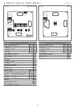
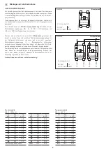
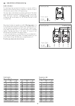
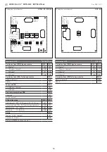
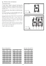
Connecting scheme
Parallel operation
Connecting scheme
Individual operation
Circuitry
Circuitry
Output
0V/GND
Output
0V/GND
Power supply
AC 24V~
0V
DC 15-36V = GND
Circuitry
Output
0V/GND
Power supply
AC 24V~
0V
DC 15-36V = GND
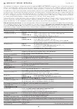
SUPPLY VOLTAGE :
For operating voltage reverse polarity protection, a one-way rectifier or
reverse polarity protection diode is integrated in this device variant.
This internal one-way rectifier on AC supply voltage.
The output signal is to be tapped by a measuring instrument. The output
signal is measured her against zero potential (O V) of the input voltage!
When this device is operated on
DC supply voltage
, the operating
voltage input UB+ is to be used for 15...36 V DC supply and UB – or GND
for ground wire!
When several devices are supplied by one 24 V
AC voltage supply
, it is
to be ensured that all ”positive“ operating voltage input terminals (+) of
the field devices are connected with each other and all ”negative“ oper-
ating voltage input terminals (–) (= reference potential) are connected
together (in-phase connection of field devices). All outputs of field
devices must be referenced to the same potential!
In case of reversed polarity at one field device, a supply voltage short-
circuit would be caused by that device. The consequential short-circuit
current flowing through this field device may cause damage to it.
Therefore, pay attention to correct wiring!

