SPACING
ADJUSTMENT
Never adjust the spacing without first adjusting DEPTH. If the depth adjustment is not right—spacing will not
be right.
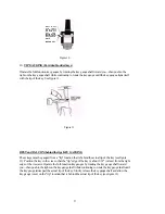
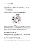
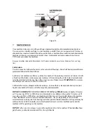
Spacing is adjusted by moving the cutter wheel and its cutter shaft assembly left or right. The cutter shaft
assembly is secured to the machines main housing by one #10-32 Alien Socket Head Cap Screws. See figure
16. To adjust spacing you will need:
• 5/32" Alien Hex Wrench
• Two identical Key Blanks
• Small Plastic Mallet
Before you begin please make sure that both top vise jaws are in the standard configuration.
Figure 16
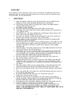
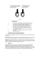
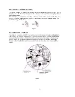
Stack the two identical key blanks one on top of the other and clamp them in the right hand vise jaw. Be
sure to top shoulder gauge them with the machine's full-function key gauges—leave the 1/32" gap between
the bottom shoulder of the keys and the left-side edge of the vise jaws. DO NOT bottom shoulder the keys
into the vise—there may be a small radius in the corner of the key blank's blade and bottom shoulder area.
Clamping in this area may ANGLE the key blank in the vise and throw off your adjustment.
There should be NO key blank in the left vise jaw for this part of the procedure.
DO NOT FORGET
to flip up your key gauges.
Switch ON the key machine and carefully release the carriage and position it so the cutter wheel will make
a cut in about the middle of the blade of the key blanks. Hold the machine's carriage steady and carefully
make a straight "V" cut into the two-piece key blank stack about 1/8" deep—it is important to do this
operation without moving the carriage sideways by the slightest amount.
Pull the carriage back straight and switch OFF the key machine.
Remove the two key blanks from the right vise jaw—Do Not Mix Them Up.
Reinstall the TOP key blank in the right vise jaw with about 1/32" gap between the bottom shoulder of the
key and the left-edge of the vise jaw.
13
14.
#10-32 SCREW-


