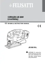
background image

14

ASSEMBLY

Fig. 7

MOUNTING 

SURFACE

 BASE

TRACE HOLES 

AT THESE LOCATIONS 

FOR HOLE PATTERN

TRACE HOLES  

AT THESE LOCATIONS 

FOR HOLE PATTERN

WARNING:

Do not start the compound miter saw without checking for 
interference between the blade and the miter fence. Damage 
could result to the blade if it strikes the miter fence during 
operation of the saw.

WARNING:


This saw can tip over if the saw head is released suddenly 
and  the  saw  is  not  secured  to  a  work  surface.  ALWAYS 
secure this saw to a stable work surface before any use to 
avoid serious personal injury.

MOUNTING HOLES

See Figure 7.

WARNING:

Always  make  sure  the  compound  miter  saw  is  securely 
mounted  to  a  workbench  or  an  approved  workstand. 
Failure  to  heed  this  warning  can  result  in  serious 
personal injury.

The  compound  miter  saw  should  be  mounted  to  a  firm  
supporting  surface  such  as  a  workbench.  Four  bolt  holes 
have  been  provided  in  the  saw  base  for  this  purpose.  Each 
of  the  four  mounting  holes  should  be  bolted  securely  using  
3/8  in.  machine  bolts,  lock  washers,  and  hex  nuts  (not  
included). Bolts should be of sufficient length to accommodate 
the saw base, lock washers, hex nuts, and the thickness of the 
workbench. Tighten all four bolts securely.
The hole pattern for mounting to a workbench is shown in fig-
ure 7. Carefully check the workbench after mounting to make 
sure that no movement can occur during use. If any tipping, 
sliding, or walking is noted, secure the workbench to the floor 
before operating.

UNPACKING

This product requires assembly.

  Carefully lift saw from the carton by the carrying handle and 

the saw base, and place it on a level work surface.


NOTE:

 This tool is heavy. To avoid back injury, lift with your 

legs, not your back, and get help when needed.

  This saw has been shipped with the saw arm secured in the 

down position. To release the saw arm, push down on the top 
of the saw arm, cut the tie-wrap, and pull out on the lock pin.

  Lift  the  saw  arm  by  the  handle.  Hand  pressure  should 

remain  on  the  saw  arm  to  prevent  sudden  rise  upon  
release of the tie wrap.

  Inspect the tool carefully to make sure no breakage or dam-

age occurred during shipping.

  Do not discard the packing material until you have carefully 

inspected and satisfactorily operated the tool.

  The  saw  is  factory  set  for  accurate  cutting.  After 

assembling  it,  check  for  accuracy.  If  shipping  has  
influenced  the  settings,  refer  to  specific  procedures  
explained in this manual.

  If  any  parts  are  damaged  or  missing,  please  call 

1-800-525-2579 for assistance.

WARNING:

If any parts are missing, do not operate this tool until the 
missing parts are replaced. Failure to do so could result in 
possible serious personal injury.

WARNING:

Do not attempt to modify this tool or create accessories not 
recommended  for  use  with  this  tool.  Any  such  alteration 
or modification is misuse and could result in a hazardous 
condition leading to possible serious personal injury.

WARNING:

Do  not  connect  to  power  supply  until  assembly  is 
complete. Failure to comply could result in accidental start-
ing and possible serious personal injury.

Summary of Contents for TS1342

Page 1: ...ineered and manufactured to our high standard for dependability ease of operation and op erator safety When properly cared for it will give you years of rugged trouble free performance WARNING To redu...

Page 2: ...teries are warranted for two years HOW TO GET SERVICE Just return the power tool properly packaged and postage prepaid to an Authorized Service Center You can obtain the location of the Service Center...

Page 3: ...FETY GLASSES WITH SIDE SHIELDS Everyday eyeglasses have only impact resistant lenses they are NOT safety glasses SECURE WORK Use clamps or a vise to hold work when practical it is safer than using you...

Page 4: ...PIECE Never start the saw with the blade touching the workpiece Allow motor to come up to full speed before starting cut NEVER cut more than one piece at a time DO NOT STACK more than one workpiece on...

Page 5: ...ALWAYS STAY ALERT Do not allow familiarity gained from frequent use of the saw to cause a careless mistake ALWAYS REMEMBER that a careless frac tion of a second is sufficient to inflict severe injury...

Page 6: ...peed orbits etc per minute Do not expose to rain or use in damp locations To reduce the risk of injury user must read and understand operator s manual before using this product Eye Protection Precauti...

Page 7: ...can result in severe eye damage Before beginning power tool operation always wear safety goggles or safety glasses with side shields and when needed a full face shield We recommend Wide Vision Safety...

Page 8: ...before each use If damaged replace immediately Never use tool with a damaged cord since touching the damaged area could cause electrical shock resulting in serious injury ELECTRICAL DOUBLE INSULATION...

Page 9: ...g dropped into the blade or being placed inadvertently in contact with the blade Workpiece or Material The item on which the operation is being done Worktable Surface where the workpiece rests while p...

Page 10: ...Maximum nominal lumber sizes 2 x 4 Cutting Capacity with Miter at 0 Bevel 45 Maximum nominal lumber sizes 2 x 6 Cutting Capacity with Miter at 45 Bevel 45 Maximum nominal lumber sizes 2 x 4 Fig 1 LOWE...

Page 11: ...ted in the saw s base CARRYING HANDLE See Figure 2 For convenience when carrying or transporting the miter saw from one place to another a carrying handle has been provided on top of the saw arm To tr...

Page 12: ...en provided to quickly stop blade rotation after the switch is released MITER FENCE The miter fence on the compound miter saw has been provided to hold the workpiece securely against when making all c...

Page 13: ...essories not listed might be hazardous and could cause serious personal injury The following items are included with the tool Miter Lock Handle Dust Bag Work Clamp Blade Wrench Operator s Manual Fig 6...

Page 14: ...the workbench to the floor before operating UNPACKING This product requires assembly Carefully lift saw from the carton by the carrying handle and the saw base and place it on a level work surface NO...

Page 15: ...e fence or the saw table It also prevents the workpiece from creeping toward the saw blade This is very helpful when cutting compound miters Depending on the cutting operation and the size of the work...

Page 16: ...asher and outer blade washer where they contact the blade WARNING If inner blade washer has been removed replace it before placing blade on spindle Failure to do so could cause an accident since blade...

Page 17: ...ay a framing square flat on the miter table Place one leg of the square against the fence Place the other leg of the square beside the throat plate in the miter table The edge of the square and the th...

Page 18: ...w blade angles away from the square as shown in figures 18 and 19 adjust ments are needed Loosen the socket head screws that secure the miter fence to the miter table Rotate the miter fence left or ri...

Page 19: ...ring positive stop adjustment screw Also loosen bevel lock knob Adjust positive stop adjustment screw to bring saw blade into alignment with the square See Positive Stop Adjustment in the Adjustment s...

Page 20: ...ly before making a cut Failure to do so could result in movement of the control arm or miter table while making a cut WARNING To avoid serious personal injury keep hands outside the no hands zone at l...

Page 21: ...res 25 26 Abevelcutismadebycuttingacrossthegrainoftheworkpiece with the blade angled to the workpiece A straight bevel cut is made with the miter table set at the zero degree position and the blade se...

Page 22: ...the desired cut The firstanglesettingshouldbecheckedaftersettingthesecond angle since adjusting the second angle affects the first Once the two correct settings for a particular cut have been obtaine...

Page 23: ...blade into and through the workpiece Releasetheswitchtriggerandallowthesawbladetostop rotating before raising the blade out of workpiece Wait until the electric brake stops blade from turning before...

Page 24: ...59 M 34 32 B 11 60 M 28 48 B 9 85 M 24 35 B 8 53 M 21 27 B 7 52 M 18 88 B 6 72 M 16 98 B 6 07 M 33 36 B 14 38 M 27 62 B 12 20 M 23 56 B 10 57 M 20 58 B 9 31 M 18 26 B 8 31 M 16 41 B 7 50 M 32 18 B 17...

Page 25: ...f your miter saw Fig 30 CUTTING CROWN MOLDING The compound miter saw does an excellent job of cutting crownmolding Ingeneral compoundmitersawsdoabetter job of cutting crown molding than any other tool...

Page 26: ...f molding against fence 2 Miter table set left 31 62 3 Save left end of cut Left side outside corner 1 Bottom edge of molding against fence 2 Miter table set left 31 62 3 Save right end of cut Right s...

Page 27: ...STOP The depth stop limits the blade s downward travel It allows the blade to go below the miter table enough to maintain full cutting capacities The depth stop positions the blade 1 4 in from the mi...

Page 28: ...semblies that should be periodically checked for wear Proceed as follows when replacement is required Unplug the saw WARNING Failure to unplug the saw could result in accidental start ing causing seri...

Page 29: ...29 NOTES...

Page 30: ...10 in Compound Miter Saw TS1342 Double Insulated ONE WORLD TECHNOLOGIES INC 1428 Pearman Dairy Road Anderson SC 29625 Phone 1 800 525 2579 www ryobitools com Ryobi is a registered trademark of Ryobi...

Reviews: