background image

Page 12

15˚

30˚

45˚

45˚

30˚

15˚

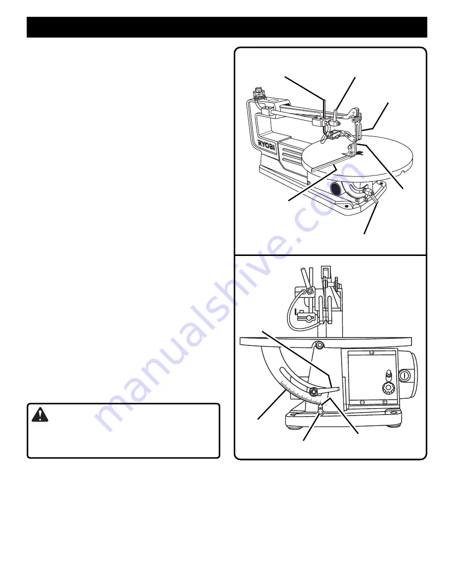
SQUARING TABLE TO THE BLADE

See Figures 8 and 9.

Loosen the hold down foot lock lever and move hold down
rod all the way up. Tighten lever.

Loosen the table lock lever and move the table until it is
approximately perpendicular, or at right angle to the
blade.

Place a small square on the table next to the blade to
check if the table is 90 degrees to the blade. If adjustment
is needed, raise or lower the table until table is 90 degrees
to the blade and securely tighten the table lock lever.

Loosen the screw holding the scale indicator, move
indicator to the 0 degree mark and securely tighten screw.
Remember, the bevel scale is a convenient guide but
should not be relied upon for precision. Make practice
cuts on scrap material to determine if your angle settings
are correct.

Adjust the hold down foot to desired position and securely
tighten the hold down foot lock lever.

SETTING THE TABLE FOR HORIZONTAL OR
BEVEL CUTTING

See Figure 9.

A bevel scale is provided under the work table as a conve-
nient guide for setting the approximate table angle for bevel
cutting. When greater precision is required, make practice
cuts on scrap material and adjust the table as necessary for
your requirements.

INSTALLING BLADES

Scroll saw blades wear out quickly and must be replaced
frequently for best cutting results. Expect to break some
blades while you learn to use and adjust your saw. Blades
generally stay sharp for 1/2 hour to 2 hours of cutting,
depending on type of material and speed of operation.

Pin End Blades
See Figures 10 and 11.

Turn off and unplug the saw from outlet.

WARNING:

To avoid injury from accidental starting, always turn off
and unplug the saw before installing, removing or replacing
the blade.

On the top back of the saw, rotate the quick release knob
to the left or counterclockwise to loosen blade tension.
See Figure 4.

Place blade through the opening with the teeth of the
blade to the front of the saw and pointing down toward the
table. Engage the pin into the "V" notch of the lower blade
holder. 

See Figure 10.

Pull up on the blade and push down on the saw arm to
engage the upper pin in the "V" notch of the upper blade
holder. 

See Figure 11.

ADJUSTMENTS

Fig. 9

TABLE LOCK

LEVER

BEVEL
SCALE

SCALE

INDICATOR

SCREW

Fig. 8

HOLD DOWN FOOT/

BLADE GUARD

HOLD DOWN FOOT

LOCK LEVER

SMALL

COMBINATION

SQUARE

SAW

BLADE

HOLD

DOWN ROD

TABLE LOCK

LEVER

Note: If the blade touches the hold down foot on either side

then the hold down foot must be adjusted.

Loosen the hold down foot lock lever. 

See Figure 8.

To center the hold down foot around the saw blade, slide
the hold down foot to the side.

Tighten the hold down foot lock lever.

To tension the blade, rotate the quick release knob (outer,
larger knob) 1/4 turn to the right or clockwise to apply
tension to the blade. Fine adjustments of the blade

Summary of Contents for SC155VS

Page 1: ...ntire operator s manual before using your new scroll saw Pay close attention to the Rules for Safe Operation Warnings and Cautions If you use your scroll saw properly and only for what it is intended...

Page 2: ...ur new saw Pay close attention to the Rules For Safe Operation and all Safety Alert Symbols including Danger Warning and Caution If you use your saw properly and only for what it is intended you will...

Page 3: ...use power tools near gasoline or other flammable liquids in damp or wet locations or expose them to rain Keep the work area well lit KEEP CHILDREN AND VISITORS AWAY All visitors should wear safety gl...

Page 4: ...arts saw stability mounting and any other conditions that may affect its operation A guard or other part that is damaged must be properly repaired or replaced by a qualified service technician at an a...

Page 5: ...e blade ALWAYS make sure you have good balance Do not cut pieces of material that are too small to hold comfortably in your hand REPLACEMENT PARTS All repairs whether electrical or mechanical should b...

Page 6: ...al voltage drop will cause a loss of power and the motor will overheat If the saw does not operate when plugged into an outlet double check the power supply GROUNDING INSTRUCTIONS In the event of a ma...

Page 7: ...e thinner pieces Resin A sticky sap base substance that has hardened Ripping A cutting operation along the length of the workpiece Saw Blade Path The area directly in line over under behind or in fron...

Page 8: ...placed Failure to do so could result in possible serious personal injury Do not discard the packing materials until you have carefully inspected the saw identified all parts and satisfactorily operate...

Page 9: ...ned to retain and position pin type blades Convenient knobs T handle wrench and blade changing rod are used for plain end blades BLADE TENSION KNOBS Blade tension is controlled by a dual knob tension...

Page 10: ...bench holes should be drilled through the supporting surface of the workbench using dimensions illustrated Each hole in the base of the saw should be bolted securely using 5 16 in diameter machine bol...

Page 11: ...orkpiece and to direct air to the cutting surface CLAMPING SCROLL SAW TO WORKBENCH See Figure 6 If the scroll saw is to be used in a portable application we recommend that you fasten it permanently to...

Page 12: ...y for best cutting results Expect to break some blades while you learn to use and adjust your saw Blades generally stay sharp for 1 2 hour to 2 hours of cutting depending on type of material and speed...

Page 13: ...e location of both the V notch and chamfer on each Carefully loosen lower blade knob until blade holder block can be removed Flip blade holder block 180 then rotate V notch up 90 as shown in figure 13...

Page 14: ...quick release knob can be either released or engaged while making adjustments with the ten sion adjusting knob Rotate quick release knob to the right or clockwise 1 4 turn to engage tension before us...

Page 15: ...utting depend ing on type of material and speed of operation To get accurate cuts be prepared to compensate for the blade s tendency to follow the wood grain as you are cutting wood In cutting wood be...

Page 16: ...injury INTERIOR SCROLL CUTTING See Figure 20 One of the features of a scroll saw is that it can be used to make scroll cuts on the interior of a board without breaking or cutting through the edge or...

Page 17: ...e another person as a substitute for a table extension or as additional support for a workpiece or to help feed support or pull the workpiece When cutting an irregularly shaped workpiece plan your wor...

Page 18: ...he workpiece and related support devices off the table before plugging into power and turning the saw on PLAN THE WAY YOU WILL HOLD THE WORKPIECE FROM START TO FINISH Do not hand hold pieces so small...

Page 19: ...tension 2 Feeding too quickly 3 Wrong blade 4 Blade twisting in wood 1 Improper mounting of saw 2 Mounting surface 3 Loose table or table resting against motor 4 Loose motor mounting 1 Blade tension r...

Page 20: ...in SCROLL SAW MODEL NUMBER SC155VS 1 2 3 4 5 6 7 8 9 11 10 12 13 14 15 16 17 18 20 19 21 22 23 26 27 28 29 30 31 32 33 25 24 34 35 35 34 37 38 38 19 37 43 42 39 40 41 44 45 46 47 48 49 50 46 45 53 52...

Page 21: ...ge 1 33 105019003 Arm Cover 1 34 104030006 Shoulder Bolt 2 35 380314300 Spring Washer 2 36 105016005 Lower Arm 1 37 420010501 Roll Pin M5 x 14 2 38 981395001 Wing Knob 2 39 101004200 Lower Blade Holde...

Page 22: ...Page 22 RYOBI 16 in SCROLL SAW MODEL NUMBER SC155VS 1 2 3 4 5 6 7 8 9 10 11 12 13 14 15 16 17 18 19 20 21 22 24 25 23 26 27 28 29 30 31 15 32 33 34 35 36 37 38 39 40 39 34 37 41 42 43 34 FIGURE B...

Page 23: ...981378001 Screw M5 x 12 Pan Hd 5 16 981375001 Control Box Cover 1 17 981372001 PC Board Assembly 1 18 979798001 Gasket 1 19 981376001 Control Box 1 20 981373001 Switch Knob 1 21 981370001 Switch Label...

Page 24: ...extension cord inspect it for loose or exposed wires and cut or worn insulation Ampere rating on tool data plate 0 2 0 2 1 3 4 3 5 5 0 5 1 7 0 7 1 12 0 12 1 16 0 Cord Length Wire Size A W G 25 16 16 1...

Reviews: