


6
ENGLISH (Original Instructions)
ASSEMBLY
JOINING THE POWER HEAD TO THE STRAIGHT
SHAFT ATTACHMENT (Fig. 2)
WARNING
Never attach or adjust any attachment while
power head is running. Failure to stop the engine
may cause serious personal injury.
The straight shaft trimmer attachment connects to the
power head by means of a coupler device.
■ Loosen the knob (6) on the coupler (7) of the power
head shaft and remove the hanger cap (5) from the
attachment shaft.
■ Push in the button located on the attachment shaft.
Align the button with the guide recess (8) on the
power head coupler and slide the two shafts together.
Rotate the attachment shaft until the button locks into
the positioning hole (9).
Note:
If the button does not release completely in the
positioning hole, the shafts are not locked into place.
Slightly rotate from side to side until the button is
locked into place.
■ Tighten the knob securely.
WARNING
Be certain the knob is fully tightened before
operating equipment; check it periodically for
tightness during use to avoid serious injury or
product damage.
FRONT HANDLE & SHOULDER STRAP (Fig. 3)
■ Adjust the position of the handle for the best balance
and comfort, securely tighten the screws with
combination wrench.
■ Connect the shoulder strap to the strap hanger
adjust to a comfortable position.
REMOVING THE ATTACHMENT FROM THE POWER
HEAD
For removing or changing the attachment:
■ Loosen the knob.
■ Push in the button and twist the shafts to remove and
separate ends.
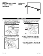
ATTACHING THE GRASS DEFLECTOR TO THE STRING
GUARD (FIG. 5)
Note:
When using the line trimming head, the grass
deflector (19) must be attached to the string guard.
■ Carefully align the locking tabs on the grass deflector
with the the slots on the string guard (3).
■
Push the grass deflector towards the string guard
until the locking tabs click firmly into place.
WARNING
The grass deflector is fitted with a line cut off
blade. Take extra care when fitting the grass
deflector to avoid contact with the sharp blade.
INSTALLING THE BUMP HEAD (FIG. 7)
■ Remove currently installed line trimmer.
■
Open the bump head by depressing the latches on
each side. The contents of the bump head are spring
loaded, so keep your other hand over the bump head
cover while depressing the latches.
■ Remove the bump head cover, bump knob, and line
spool and set aside.
■ Place the bump head housing on the drive connector.
Make sure the housing is fully seated.
■ Install the hex bolt to secure the bump head to the
drive connector. Tighten by using the hex-shaped
opening on the inside of the bump knob.
Note:
Only use the bump knob to tighten the bolt. The use
of other tools may allow over tightening of the bolt, which
could damage the bump head. (Fig. 7, image 2)
■ Reinstall the bump head spring into the bump head
and push down to seat.
■ Reinstall the line spool.
Note:
For the straight shaft attachment with the bump head,
the spool should be placed so “This side out for straight
shaft” is visible on the line spool.
■ Replace the bump knob by inserting it into the centre
of the line spool.
■ Replace the bump head cover, aligning latches with
openings in the bump head. Press cover and bump
head together until both latches snap into openings
securely.
■ Install line as described in the next section of this
manual.
INSTALLING LINE IN BUMP HEAD (FIG. 8)
Use 2.4 mm diameter monofilament line.
■ Stop the engine and disconnect the spark plug wire.
■ Cut one piece of line approximately 6.0 meters in
length.
■ Rotate the bump knob on bump head until line on the
centre of the bump knob aligns with arrows on top of
bump head.
■ Insert one end of line into eyelet located on the side
of the bump head and push until line comes out
through the eyelet on the other side. Continue to
push line through the bump head until the middle
section of the line is inside the bump head and line
outside the bump head is evenly divided on each
side.
■ Rotate the knob on the bump head to wind the line. If
Summary of Contents for EXPAND-IT ALT04G
Page 10: ...20160414v2...
Page 11: ......