background image

    BASIC SCROLL SAW OPERATIONS


BLADES

Your new scroll saw accepts 127mm pin type blades. Your
saw is also equipped with blade adaptors that allow you to
use a variety of 127mm plain end blades.

WARNING:
To prevent personal injury
always disconnect the power cord from
power source before changing blades or
making adjustments.

!

   REMOVING AND INSTALLINGPIN TYPE BLADES
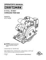
1. Rotate the blade tension knob anti-clockwise to release
blade tension.
2. Remove table insert and remove blade from the inner
upper and lower blade holders by pulling forward on blade
and then lifting the blade through the access hole in the
table. Slight downward pressure against the upper holder
may be helpful when removing blade from upper holder.
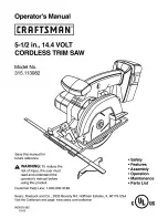
3. Look at the blade holders closely and notice the blade
slots and pin recesses in the blade hold-ers. The blade
holders are made so you can position the blade for cutting

from the front or from one side of the saw as shown. Cut-
ting from the side of the saw will be necessary when your
work piece exceeds 405mm in length. It allows your scroll
saw to cut like a band saw. For 0˚ horizontal cutting only.
4. In order to cut, and avoid uncontrollable lifting of the
workpiece, the teeth of the blade used on the scroll saw
should always point downwards when installed.
5. Install the blade while inserting one end of the blade
through the access hole in the table and hook the blade pin
in the pin recess in the lower blade holder. Slide the top
blade pin into the pin recess of the inner upper blade holder.
You may need to press down lightly on the upper blade
holder to install the blade.
6. Carefully tighten the blade by rotating the blade tension
knob clockwise just until you feel the slack in the blade
removed. Double check to see that the pins are properly
located in the blade holder. Then turn the blade tension
knob ONE full turn clockwise. This amount of blade pres-
sure should do well for most cutting operations and blades.

Cap Screw

Adaptor Guard

Blade
Pin

Blade
Positioned for
front cutting

Pin
Recesses

Blade Slots

Arm

Blade
Positioned for
side cutting

Upper Inner
Blade Holder

Table Tilted for
picture clarity

Lower Inner
Blade Holder

SLIGHT

PRESSURE

HERE

Blade
Tension Knob

LOOSEN

TIGHTEN

Page 6

Summary of Contents for ESW1240

Page 1: ...d through this entire owner s manual before using your Scroll Saw SAVE THIS MANUAL FOR FUTURE REFERENCE Pay close attention to the Rules for Safe Operation Warnings and Cautions If you use your Scroll...

Page 2: ...ou are tired Do not rush operation of tool 19 CHECK DAMAGED PARTS Before further use of the tool a guard or any other part that is damaged should be carefully checked to determine that it will operate...

Page 3: ...0mm vacuum hose into the hole provided for convenient sawdust removal 4 DROP FOOT The foot should always belowered until it just rests on top of theworkpiece to prevent workpiece from lifting but not...

Page 4: ...de Tension Knob 6 Blade Length Gauge 9 Drop Foot Lock Knob 5 Adjustable Light 12 Sawdust Blower 2 Drop Foot 4 Table 1 ON Off and Variable Speed Switch 11 Vacuum Hook Up 3 Table Lock Knob 7 Degree Scal...

Page 5: ...t a right angle to the blade 2 Place a small square on the table next to the blade as shown to check if the table is 90 to the blade If adjustment is needed raise or lower the table until table is app...

Page 6: ...ce exceeds 405mm in length It allows your scroll saw to cut like a band saw For 0 horizontal cutting only 4 In order to cut and avoid uncontrollable lifting of the workpiece the teeth of the blade use...

Page 7: ...ide Cutting 1 Remove both setscrews from each blade adap tor thread them into the opposite holes in the blade adaptor perpen dicular to the adjustment pin and repeat steps 1 2 3 of above with the blad...

Page 8: ...the upper blade holder You may need to press down lightly on the upper blade holder to install the blade 4 In order to cut and avoid uncontrollable lifting of the workpiece the teeth of the blade used...

Page 9: ...d vibration will be more notice able 2 Hardware to mount his saw to a workbench is NOT SUP PLIED with the saw However we rec ommend the hard ware used be no smaller than the following Quantity Descrip...

Page 10: ...rings with oil after 10 hours of use Re oil after every 50 hours of use or when ever there is a squeak com ing from the bearings To Lubricate 1 Turn saw on its side 2 Squirt a generous amount of SAE 2...

Page 11: ...ceagent Any attempt to repair this motor may cre ate a hazard unless repair is done by a qualified service technician Vibration NOTE There will always be some vibration present when the saw is running...

Page 12: ...are in the opinion of the Company and such guarantee does not cover damage malfunction or failure resulting from misuse neglect abuse or used for a purpose for which it was not designed or is not suit...

Reviews: