


15
WINCH PARTS LIST
EWP4500
No.
Part #
Qty
Description
Remark
1
P0450001
2
Terminal Protector
2
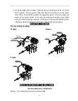
P0450100-D
1
Motor Assembly
Used in D and A type winch
P0450100-U
Used in U type winch
3
P0450002
1
Screw M4 x16
4
P0450003
2
Locking Washer Φ4
5
P0450004
1
Stand Bar
6
P0450005
1
Coupling
Ⅰ
7
P0450006
1
Spring
8
P0450007
1
Coupling
Ⅱ
9
P0450008
1
Spring
10
P0450009
2
Ring Seals
11
P0450010
2
Bushing-Drum
12
P0450011
1
Hexagonal Shaft
13
P0450012
1
Screw M6 x 8
14
P0450200
1
Drum Assembly
15
P0450013
1
End Bearing
16
P0450014
1
Screw M4 x25
17
P0450015
1
Gasket
18
P0450016
1
Gear-Ring
19
P0450300
1
Gear Carrier Assembly(Output)
20
P0450400
1
Gear Carrier Assembly(Intermediate)
21
P0450500
1
Gear Carrier Assembly(Input)
22
P0450017
1
Gear
—
Input Sun
23
P0450018
1
Gasket
24
P0450600
1
Clutch Handle Assembly
25
P0450019
4
Thick Flat Washer
Φ6
26
P0450020
6
Locking Washer Φ6
27
P0450021
2
Screw M6 x100
28
P0450022
4
Screw M6 x25
29
P0450023
2
Tie Bar
30
P0450024
2
Hex Flange Nut M10
31
P0450700
1
Roller Fairlead
32
P0450025
1
Mounting Channel
33
P0450026
2
Screw M10 x 20
34
P0450027
4
Thick Flat Washer
Φ8
35
P0450028
4
Locking Washer Φ8
36
P0450029
4
Screw M8 x25
37
P0450800
1
Cable Assembly
38
P0450030
1
Strap
39
P0450900
1
Control Section Of D Type Winch
By choice
40
P0451000
1
Control Section Of A Type Winch
By choice
41
P0451100
1
Control Section Of U Type Winch
By choice


