background image


Anchor  Strap/Chain 

–  Tree  saver  anchor  straps  are  made  of  high  quality  nylon  with 

high tensile strengths from 5,000lbs to 10,000lbs. 

Heavy Blanket 

– place on the cable to absorb energy should the wire rope break. 

RIGGING TECHNIQUES 

Self-Recovery 

Locate a suitable anchor such as a strong tree trunk or boulder.   

Always use a sling as an anchor point.  

CAUTION

 Do not attach 

the clevis hook back onto the cable as this could cause damage to 

the cable.As shown in Fig 3.1 


CAUTION

  Do  not  winch  from  an  acute  angle  as  the  wire  rope 

will  pile  up  on  one  side  of  the  drum  causing  damage  to  wire  rope 

and the winch.  Fig 3.2 

Short  pulls  from  an  angle  can  be  used  to  straighten  the  vehicle.  

Long pulls should be done with the wire rope at a 90° angle to the 

winch/vehicle. 


When pulling a heavy load, place a blanket or jacket over the wire 

rope five or six feet from the hook.  In the event of a broken cable it 

will  dampen  the  snap  back.    For  additional  protection  open  the 

hood of the vehicle as shown in Fig 3.3 


For  pulls  over  70%  rated  line  pull,  we  recommend  the  use  of  the 

snatch block/pulley block to double line the wire rope.  Fig 3.4 

This reduces the load on the winch and the strain on the rope by up 

to 50% depending on the included angle. 


WARNING  - 

Never use your winch for overhead hoisting or for 

lifting people or moving people.    


Fig 3.1 


Fig 3.2 


Fig 3.3 


Fig 3.4 


Fig 3.5 

Summary of Contents for EWP2500

Page 1: ...ELECTRIC WINCH EWP2500 EWP3500 EWP4500 Assembly Operating Instructions...

Page 2: ...NG 8 WINCH ACCESSORIES YOU WILL NEED 8 RIGGING TECHNIQUES 9 WINCH WORKING DEMONSTRATION 1 0 REPLACING THE WIRE ROPE 1 0 MAINTENANCE 1 1 TROUBLE SHOOTING 1 1 WINCH ASSEMBLY DRAWING EWP2500 EWP3500 1 2...

Page 3: ...itten for your safety Ultimately safe operation of this device rests with you the operator This indicates a potentially hazardous situation which if not avoided may result in minor or moderate injury...

Page 4: ...is a load on the wire rope A separate mechanical brake applies the braking action 8 Control System Your winch was made to provide you the ability to use it in a medley of operations The winch can be c...

Page 5: ...fe distance to the side of the cable when it is under tension WARNING The wire rope may break before the motor stalls For heavy loads at or near rated capacity use a pulley block snatch block to reduc...

Page 6: ...Duration of winching pulls should be kept as short as possible If the motor becomes uncomfortably hot to the touch stop winching immediately and let it cool down for a few minutes Do not pull for more...

Page 7: ...cifications Inspect the winch installation and bolts to ensure that all bolts are tight before each operation Never connect the cable back to itself This will cause cable damage Always use a snatch bl...

Page 8: ...ake sure all spectators are back and that no one is directly in front or behind the vehicle or anchor point o Begin winching Be sure that the wire rope is winding evenly and tightly around the drum Th...

Page 9: ...el using 2 each of the cap screw assembly Make sure the screw is placed through the mounting channel and roller fairlead from inside the channel This will allow enough clearance for the winch to be pl...

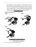
Page 10: ...your connections are accurate If the drum is turning and collecting more cable then reverse the leads on the motor Repeat and check rotation MOUNTING DRAWING The mounting drawing D type A type Switch...

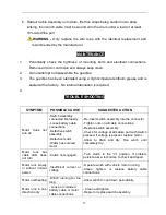
Page 11: ...wire rope and the winch Fig 3 2 Short pulls from an angle can be used to straighten the vehicle Long pulls should be done with the wire rope at a 90 angle to the winch vehicle When pulling a heavy lo...

Page 12: ...the motor stops before reversing directions 7 When the pulling is complete remove the switch assembly From the female connector of the directional valve and replace the female connectors cover Note F...

Page 13: ...onnected improperly Loose battery cable connections Defective switch assembly Defective motor Water has entered motor Re Insert switch assembly into the connector Tighten nuts on all cable connections...

Page 14: ...12 WINCH ASSEMBLY DRAWING EWP2500 EWP3500 2 17 16 15 13 14 12 10 6 8 9 4 3 5 7 2 1 11 29 18 19 20 21 22 23 24 25 26 34 33 35 30 31 32 36 32 31 30 O U T IN IN O U T 40 41 42 37 38 39 8 7 8 43 44 45...

Page 15: ...ch axes 21 P0250019 1 Cam Clutch Gear 22 P0250020 1 Spring 23 P0250021 1 Cover Clutch Housing 24 P0250022 1 Nylon Bearing 25 P0250023 1 Elastic Collar 26 P0250024 1 Clutch Handle 27 P0250025 1 Locking...

Page 16: ...14 WINCH ASSEMBLY DRAWING EWP4500 O U T IN IN O U T...

Page 17: ...300 1 Gear Carrier Assembly Output 20 P0450400 1 Gear Carrier Assembly Intermediate 21 P0450500 1 Gear Carrier Assembly Input 22 P0450017 1 Gear Input Sun 23 P0450018 1 Gasket 24 P0450600 1 Clutch Han...

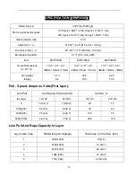
Page 18: ...4 5 4 4 323mm 113mm 112mm 12 7 4 5 4 4 323mm 113mm 112mm 13 2 4 5 6 5 335mm 113mm 165mm Net weight Ibs kg 19 8 9 0 20 5 9 3 20 5 9 3 Pull Speed Amperes Volts First layer Line Pull Line Speed ft min m...

Page 19: ...35mm 116mm 112mm 13 2 4 6 4 4 335mm 116mm 112mm 13 7 4 6 6 5 348mm 116mm 165mm Net weight Ibs kg 21 3 9 6 22 0 10 0 22 0 10 0 Pull Speed Amperes Volts First layer Line Pull Line Speed ft min m min Cur...

Page 20: ...5mm 123mm 16 1 4 92 4 85 408mm 125mm 123mm 16 1 4 92 6 6 408mm 125mm 168mm Net weight Ibs kg 33 3 15 1 34 2 15 5 34 2 15 5 Pull Speed Amperes Volts First layer Line Pull Line Speed ft min m min Curren...

Reviews: