background image

RG-IS2700G Series Switch Hardware Installation and Reference Guide 


2.4  Lightning Resistance Considerations 

When the AC power cable is imported outdoors and directly connected to the power port of the switch, lightning line bank 

should be adopted to prevent the switch from being hit by lightning shocks. The lightning line bank can be fixed on the 

cabinet, work station, or the equipment room's wall through line buckles and screws. In applications, the AC first enters 

the lightning line bank and then the switch. 


The lightning line banks are not provided and should be purchased by users as required. 


For the usage of lightning line banks, refer to their related manuals. 

2.5  EMI Consideration 

Various interference sources, from either outside or inside the equipment or application system, affect the system in the 

conductive ways such as capacitive coupling, inductive coupling, and electromagnetic radiation. 

Summary of Contents for RG-IS2706G

Page 1: ...RG IS2700G Series Switch Hardware Installation and Reference Guide V1 12 ...

Page 2: ... or by any means without the prior written consent of Ruijie Networks is prohibited Exemption Statement This document is provided as is The contents of this document are subject to change without any notice Please obtain the latest information through the Ruijie Networks website Ruijie Networks endeavors to ensure content accuracy and will not shoulder any responsibility for losses and damages cau...

Page 3: ...btaining Technical Assistance Ruijie Networks Website http www ruijienetworks com Service Email service_rj ruijienetworks com Technical Support http www ruijienetworks com service aspx Technical Support Hotline 86 4008 111 000 Related Documents Documents Description Configuration Guide Describes network protocols and related mechanisms that supported by the product with configuration examples Comm...

Page 4: ... RG IS2700G series Model 10 100 1000Base T adaptive Ethernet port 1000Base X SFP port Console port RG IS2712G 8 4 1 RG IS2706G 4 2 1 1 1 RG IS2712G Technical Specifications Table 1 2 Technical specifications of the RG IS2712G Switches Model RG IS2712G Module Type Gigabit Ethernet MINI GBIC SX MM850 MINI GBIC LX SM1310 MINI GBIC LH40 SM1310 MINI GBIC ZX50 SM1550 MINI GBIC ZX80 SM1550 MINI GBIC ZX10...

Page 5: ...VDC to 340VDC Maximum voltage range 130VDC to 370VDC Rated current 0 4A Power Consumption Max 12 W Operating Temperature 40º C to 85º C Storage Temperature 40º C to 85º C Operating Humidity 10 to 90 RH non condensing Storage Humidity 10 to 90 RH non condensing Fan Fanless Temperature Warning Support IP Rating IP40 EMI GB 9254 2008 FCC Part 15 CISPR EN55022 class A EMS IEC EN 61000 4 2 ESD Contact ...

Page 6: ... x D x H 160 mm x 115 mm x 52 mm Weight 1 kg RG IS2712G switch is a class A product In a domestic environment this product may cause radio interference in which case the user may be required to take adequate measures Product Appearance The front panel of the RG IS2712G Ethernet switch provides eight 10 100 1000Base T Ethernet ports four Gigabit SFP fiber ports and one Console port The back panel p...

Page 7: ...RG IS2700G Series Switch Hardware Installation and Reference Guide Front Panel Figure 1 2 RG IS2712G Front Panel ...

Page 8: ...tive Ethernet port indicator 5 10 100 1000Base T adaptive Ethernet port 6 1000Base X SFP port 2 5 G stack port 7 1000Base X SFP port indicator 8 Power interface Side panel Figure 1 3 RG IS2712G Side Panel Note 1 6 pin AC power connector 2 Grounding pole 3 Warning Label for high temperature and electric shock Back panel Figure 1 4 RG IS2712G Back Panel ...

Page 9: ...bel 2 Device bar code 3 DIN slot 4 Network access license of the device 5 MAC address of the device 6 Tips for software preinstallation Power Supply The RG IS2712G switch adopts the AC power input AC input Rated voltage range 100 VAC to 240 VAC Maximum voltage range 85 VAC to 265 VAC Frequency 50 Hz to 60 Hz ...

Page 10: ...rs Solid green The switch is operational Solid yellow It indicates a warning on the switch temperature Check the working environment of the switch immediately Solid red Indicates a fault on the switch For details refer to Section of Troubleshooting Common Faults RJ 45 port indicator 1 8 Off No link or port was administratively shut down Solid green Link present Blinking green Activity The port is ...

Page 11: ...FP Port Supporting 1000Base X Supporting 2 5Gbps bandwidth and VSU deployment Power Supply AC input Rated voltage range 100VAC to 240VAC Maximum voltage range 90VAC to 264VAC Frequency 50Hz to 60Hz Rated current 0 5A HVDC input Rated voltage range 140VDC to 340VDC Maximum voltage range 130VDC to 370VDC Rated current 0 4A Power Consumption Max 11 5W Operating Temperature 40º C to 85º C Storage Temp...

Page 12: ...B4943 2011 Dimensions W x D x H 160 mm x 115 mm x 52 mm Weight 1kg RG IS2706G switch is a class A product In a domestic environment this product may cause radio interference in which case the user may be required to take adequate measures Product Appearance The front panel of the RG IS2706G Ethernet switch provides four 10 100 1000Base T Ethernet ports two Gigabit SFP fiber ports and one Console p...

Page 13: ... Panel Note 1 Switch status indicator 2 Reset button 3 Console port 4 10 100 1000Base T adaptive Ethernet port indicator 5 10 100 1000Base T adaptive Ethernet port 6 1000Base X SFP port 2 5 G stack port 7 1000Base X SFP port indicator 8 Power interface Side panel Figure 1 7 RG IS2706G Side Panel ...

Page 14: ...00G Series Switch Hardware Installation and Reference Guide Note 1 6 pin AC power connector 2 Grounding pole 3 Warning Label for high temperature and electric shock Back panel Figure 1 8 RG IS2706G Back Panel ...

Page 15: ... slot 10 Network access license of the device 11 MAC address of the device 12 Tips for software preinstallation Power Supply The RG IS2706G adopts the AC power input AC input Rated voltage range 100 VAC to 240 VAC Maximum voltage range 90VAC to 264VAC Frequency 50 Hz to 60 Hz Rated current 0 5A Power cord specification 10 A power cord ...

Page 16: ...s a warning on the switch temperature Check the working environment of the switch immediately Solid red Indicates a fault on the switch For details refer to Section of Troubleshooting Common Faults RJ 45 port indicator 1 4 Off No link or port was administratively shut down Solid green Link present Blinking green Activity The port is receiving or sending data SFP port indicator 5F 6F Off No link or...

Page 17: ... 2 5Gbps bandwidth and VSU deployment Power Supply DC input Rated voltage 24VDC 48VDC Maximum voltage range 18VDC to 72VDC Maximum current 1 0A Two power supplies are supported for 1 1 power redundancy Power Consumption Max 12 W Operating Temperature 40º C to 85º C Storage Temperature 40º C to 85º C Operating Humidity 10 to 90 RH non condensing Storage Humidity 10 to 90 RH non condensing Fan Fanle...

Page 18: ... In a domestic environment this product may cause radio interference in which case the user may be required to take adequate measures Product Appearance The front panel of the RG IS2712G DC Ethernet switch provides eight 10 100 1000Base T Ethernet ports four Gigabit SFP fiber ports and one Console port The back panel provides AC power input ports Figure 1 1 shows the appearance of the RG IS2712G D...

Page 19: ...h status indicator 2 Reset button 3 Console port 4 10 100 1000Base T adaptive Ethernet port indicator 5 10 100 1000Base T adaptive Ethernet port 6 1000Base X SFP port 2 5 G stack port 7 1000Base X SFP port indicator 8 Power interface Side panel Figure 1 11 RG IS2712G DC Side Panel ...

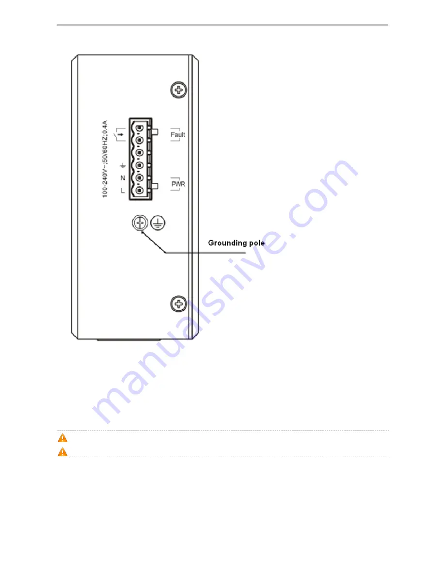
Page 20: ...Series Switch Hardware Installation and Reference Guide 1 2 3 Note 1 Six pin power connector 2 Grounding pole 3 Warning Label for high temperature and electric shock Back panel Figure 1 12 RG IS2712G DC Back Panel ...

Page 21: ...dopts the DC power input Two power supplies are supported for 1 1 power redundancy DC input Rated voltage 24VDC 48VDC Maximum voltage range 18VDC to 72VDC Maximum current 0 1A Heat Dissipation The RG IS2712G DC switch is designed with no fans To ensure good dissipation sufficient ventilation space 10 cm distances from both sides and the back panel of the chassis should be reserved to avoid the air...

Page 22: ...d yellow It indicates a warning on the switch temperature Check the working environment of the switch immediately Solid red Indicates a fault on the switch For details refer to Section of Troubleshooting Common Faults RJ 45 port indicator 1 8 Off No link or port was administratively shut down Solid green Link present Blinking green Activity The port is receiving or sending data SFP port indicator ...

Page 23: ...e the power sockets and cables before dismantling the cabinet 2 1 2 Movement Safety Do not frequently move the device When moving the device note the balance and avoid hurting legs and feet or straining the back Before moving the device turn off all power supplies and dismantle all power modules 2 1 3 Electric Safety Observe local regulations and specifications when performing electric operations ...

Page 24: ...To ensure the normal working and a prolonged durable life of the equipment the installation site must meet the following requirements 2 2 1 Ventilation Requirements For the RG IS2700G series you must ensure that sufficient space at least 10cm distance from both sides of the cabinet is reserved at the ventilation openings to ensure the normal ventilation After various cables have been connected the...

Page 25: ...ts for the dust content and granularity Table 2 2 Maximum diameter μm 0 5 1 3 5 Maximum density Particles m 3 1 4 x 10 7 x 10 2 4 x 10 1 3 x 10 Apart from dust the salt acid and sulfide in the air must also meet strict requirements as such poisonous substances may accelerate the corrosion of the metal and the aging of some parts The harmful gases such as sulfur dioxide sulfured hydrogen nitrogen d...

Page 26: ...ed with precision 2 3 1 Safety Grounding The equipment using AC power supply must be grounded by using the yellow green safety grounding cable Otherwise when the insulating resistance decreases the power supply and the enclosure in the equipment electric shock may occur 2 3 2 Lightning Grounding The lightning protection system of a facility is an independent system that consists of the lightning r...

Page 27: ...binet work station or the equipment room s wall through line buckles and screws In applications the AC first enters the lightning line bank and then the switch The lightning line banks are not provided and should be purchased by users as required For the usage of lightning line banks refer to their related manuals 2 5 EMI Consideration Various interference sources from either outside or inside the...

Page 28: ... the switch should be preferably separated and kept as far as possible from the grounding device of the power equipment or the anti lightning grounding device Keep the equipment away from high power radio transmitter radar transmitting station and high frequency large current device Measures must be taken to shield static electricity 2 6 Precaution for Fiber Connections Before you connect the fibe...

Page 29: ...n Procedure 3 2 Confirmations before Installation Before installation please confirm the following points Sufficient airflow is available for the switch The Requirements of the switch for temperature and humidity are met Power cables are already laid out and whether the requirements of electrical current are met Related network adaption lines are already laid out 3 3 Installing the RG IS2700G Seri...

Page 30: ...tion Do not stack the devices The switch should be located at places free from the direct sunlight large power radio launch pad radar launch pad and high frequency large current devices If necessary electromagnetic shielding should be adopted For example use interface cables to shield cables 3 3 2 Mounting the Switch on a DIN Rail 1 Place the switch on the site where has sufficient space for heat ...

Page 31: ...RG IS2700G Series Switch Hardware Installation and Reference Guide Figure 3 4 3 3 3 Mounting the Switch with a Vertical Bracket 1 Remove the four screws from the rear panel of the switch Figure 3 5 ...

Page 32: ...holes on the rear panel of the switch and tighten the mounting screws Keep the round screw holes on the vertical bracket downward Figure 3 6 3 Mark the location of round screw mounting holes then remove the switch Drill holes at the marked location Insert the anchors into the holes then mount the switch with tapping screws Figure 3 7 4 Pull down the switch slightly to complete the mounting ...

Page 33: ...power cord into the 6 pin connector as shown in Figure 3 8 1 indicates the protective earth PE ground wire which is green with yellow strip 2 indicates the neutral wire N wire which is green or blue 3 indicates the line voltage wire L wire which is red or brown Figure 3 8 2 Turn bolts on the connector clockwise and plug the connector into the switch Figure 3 9 ...

Page 34: ...uide Figure 3 10 3 3 4 2 RG IS2712G DC 1 Two two pin wires are needed Insert the power cords into the 6 pin connector as shown in Figure 3 11 V1 and V2 red wires indicate the positive poles of power supplies while V1 and V2 black wires indicate the negative poles ...

Page 35: ...power supplies are supported for 1 1 power redundancy 3 4 Checking after Installation Before checking the installation switch off the power supply so as to avoid any personal injury or damage to the component due to connection errors Check that the ground line is connected Check that the cables and power input cables are correctly connected Check that sufficient airflow is available around the dev...

Page 36: ... console cable to the serial port of the PC Step 2 Connect one end of the console cable RJ45 to the console port of the switch 4 1 2 Setting Terminal Parameters Step 1 Start the PC and run the terminal simulation program on the PC such as Terminal on Windows 3 1 or HyperTerminal on Windows 95 98 NT 2000 XP Step 2 Set terminal parameters The parameters are as follows baud rate 9600 data bit 8 parit...

Page 37: ...K A window appears as shown in Figure 4 3 In the Connect Using field select the serial port you want to use Figure 4 3 After selecting the serial port click OK The Serial Port Parameter Setting window is displayed as shown in Figure 4 4 Set the baud rate to 9600 data bit to 8 parity check to none stop bit to 1 and flow control to none Figure 4 4 ...

Page 38: ...er supply voltage complies with the requirement of the switch The console cable is correctly connected the terminal can be a PC used for configuration is already started the parameters are already configured Checking after Power on Recommended After power on you are recommended to perform the following checks to ensure the normal operation of follow up configurations Check that information is disp...

Page 39: ...partment for technical support The status indicator is not on after the switch is started The power supply module does not supply power The power cable is in loose contact Check whether the power socket at the equipment room is normal and whether the power cable of the switch is in good contact The status indicator is red Temperature alarm At this time the switch already stops the normal service e...

Page 40: ...us in receiving transmitting frames The connected twisted pair cable is faulty The length of the cable exceeds 100 m The port has special configuration that has no common working mode with the connected switch Replace the twisted pair cable Check that the port configuration has the common working mode with the connected switch The fiber port cannot be connected The Rx and Tx ends are connected rev...

Page 41: ...four pairs of wires for transmission all of which must be connected 0 shows the connections of the twisted pairs used by the 1000BASE T port Figure A 1 Schematic diagram for the four twisted pairs of the 1000BASE T In addition to the above cables the 100BASE TX 10BASE T can also use 100 ohm Category 3 4 5 cables for 10 Mbps and 100 ohm Category 5 cables for 100 Mbps both of which can be up to 100 ...

Page 42: ...and Reference Guide Fiber Optic Connection For fiber ports select single mode or multimode fibers for connection according to the fiber module connected The connection schematic diagram is shown in 0 Figure A 4 Schematic diagram for fiber connection ...

Page 43: ... 3 No MINI GBIC LH40 SM13 10 1310 SMF 2 LC 9 125 40km 2 3 22 3 Yes MINI GBIC ZX50 SM15 50 1550 SMF 2 LC 9 125 50km 5 0 22 3 Yes MINI GBIC ZX80 SM15 50 80km 0 4 7 22 3 MINI GBIC ZX100 SM1 550 100km 0 5 30 9 GE eSFP SX MM850 850 MMF 1 LC 62 5 125 275m 9 5 3 17 0 Yes 50 125 550m GE eSFP LX SM1310 1310 SMF 2 LC 9 125 10km 9 5 3 20 3 Yes GE SFP LX20 SM1310 BIDI 1310TX 1550RX SMF 2 LC 9 125 20km 9 3 20 ...

Page 44: ...e Diameter A WG Data Rate G b s DDM Yes No GE SFP STACK1 6M Passvie Cable SFP 1 6m 28 2 5G No Please pay attention to ESD protection when handling copper cables Please make sure the bend radius of the copper cable is not less than 8 times of its diameter Table B 3 Pairing Models of the SFP BIDI Optic Module Rate Distance Paring Models 1G 20km GE SFP LX20 SM1310 BIDI GE SFP LX20 SM1550 BIDI 1G 40km...

Reviews: