background image

·


Hardware Installation and Reference Guide                                                                                          System Debugging 


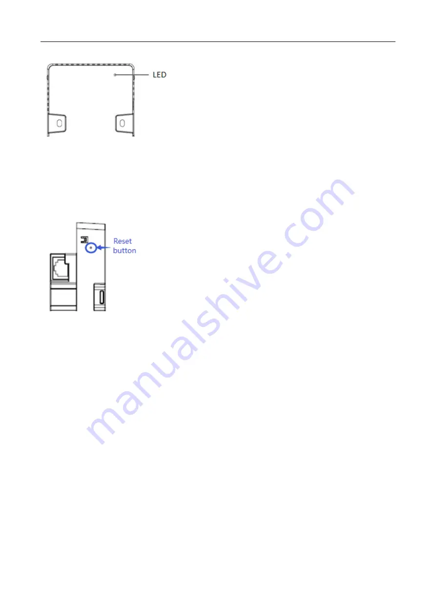
4.1.2  Reset/Restore Default Settings 

The reset button is hidden in a hole and used by technical support personnel. To avoid abnormal operation, do not use 

this button without consultation with technical support personnel. 

Figure 4-3 Reset Button on the AP 


4.1.3  System Reset 

Remove the cover. Insert an iron stick, 1mm or less in diameter, into the hole, and slightly press it. After hearing a click, 

keep the stick in the same position for 2s. The system reset is complete. 

4.1.4  Restore Default Settings 

Remove the cover. Insert an iron stick, 1mm or less in diameter, into the hole, and slightly press it. After hearing a click, 

keep the stick in the same position for 3s. The system reset is complete. 


Summary of Contents for RG-AP130(W2)

Page 1: ...RG AP130 W2 Series Access Point Hardware Installation and Reference Guide V1 02...

Page 2: ...or by any means without the prior written consent of Ruijie Networks is prohibited Exemption statement This document is provided as is The contents of this document are subject to change without any n...

Page 3: ...ty http community ruijienetworks com Technical Support Email service_rj ruijienetworks com Skype service_rj ruijienetworks com Related Documents Documents Description Configuration Guide Describes net...

Page 4: ...ss Controller Series wireless data forwarding high performance security and access control can be accomplished with ease 1 1 Technical Specifications Table 1 1 Technical Specifications of RG AP130 W2...

Page 5: ...t 2A Power Consumption 8W Temperature Operating 10 C to 45 C 14 F to 113 F Storage 40 C to 70 C 40 F to 158 F Humidity Operating 10 to 95 RH non condensing Storage 5 to 95 RH non condensing Installati...

Page 6: ...ast conversion Network management SNMP v1 v2C v3 Telnet TFTP and FTP and Web management Management and Maintenance Fault detection and alarm Support Statistics and logs Support FAT FIT switchover Supp...

Page 7: ...button 2 Lock Slot 3 Micro USB management port Console 4 Keyhole 5 Pass Through port on the side 6 DC power adapter port for DC power supply 1 3 LED Indicators Figure 1 3 Indicator on the AP State Fre...

Page 8: ...onnection is established At least one client is associated 1 4 Power Sources The AP supports PoE and DC power supply PoE power supply Input voltage range 44 57V Rated current 0 25A DC power supply Inp...

Page 9: ...rs away from the seaside and do not face it toward the wind from the sea The installation site should be free from water flooding seepage dripping or condensation The installation site shall be select...

Page 10: ...ference source can be both a part of the interfered system and a completely electrically isolated unit Conducted interference results from the electromagnetic wire or signal cable connection between t...

Page 11: ...have been met 3 1 Installation Flowchart 3 2 Before You Begin To ensure normal operation and a prolonged useful life of the equipment observe the following safety precautions Install the device in a...

Page 12: ...Point Disconnect the device before install or move it Make sure that the screws are of fine quality Be sure that the equipment is installed in a place where it is easy to be observed 1 Loosen screws o...

Page 13: ...int 3 Align screw holes on both sides of the device over those on the faceplate And then tighten screws with a screwdriver Figure 3 3 Tighten Screws with a Screwdriver 4 Install the plate cover in the...

Page 14: ...rdware Installation and Reference Guide Installing the Access Point A white cover is provided for each AP And there are three more options for sale black gold and silver Figure 3 5 Cover for RG AP130...

Page 15: ...C power adapter power supply When applying DC power supply plug one end of the Ethernet cable into the PoE UpLINK port and the other end into the power adapter port on the switch 4 1 1 Powering Up the...

Page 16: ...onnel Figure 4 3 Reset Button on the AP 4 1 3 System Reset Remove the cover Insert an iron stick 1mm or less in diameter into the hole and slightly press it After hearing a click keep the stick in the...

Page 17: ...aulty Blinking green 0 4Hz The AP is operational The CAPWAP connection is OK At least one client is associated with the AP Blinking green one flash every 4 seconds The AP is operational No clients are...

Page 18: ...ble is connected Verify that the device at the other end of the Ethernet cable is working properly And then verify that the Ethernet cable is capable of providing the required data rate and is properl...

Page 19: ...imum distance of 100 meters 328 feet 1000BASE T requires all four pairs of wires be connected for data transmission as shown in Figure A 1 Figure A 1 1000BASE T Connection 10BASE T uses Category 3 4 5...

Page 20: ...Hardware Installation and Reference Guide Appendix A Connectors and Media...

Reviews: