background image


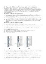
When you install the cabinet, pay attention to the following: 


All expansion bolts for fastening the cabinet base to the ground should be installed and tightened in sequence from 
bottom up (large plain washer, spring washer, and nut), and the installation holes on the base and the expansion 
bolts should be well aligned. 


After the cabinet is installed, it should be stable and still. 


After the cabinet is installed, it should be vertical to the ground. 


When multiple cabinets are put side by side in the room, they should be aligned in a straight line, with an error less 
than 5 mm. 


The front/back doors of the cabinet should be properly installed. You can open and close them smoothly. The locks 
should work normally, and all keys should be complete. 


There should be no unnecessary formal labels inside the cabinet and on various boards. 


Blank panels should be installed completely. 


Fastening screws of various devices in the cabinet of the same model should be ready and tightened. 


Various boards of the equipment should be installed securely, and the fastening screws on the panel should be 
tightened. 


All wiring inlets at the top and bottom of the cabinet should be installed with rodent-resistant nets where the seams 
should be no more than 1.5 cm in diameter, to prevent rodents and other small animals from entering the cabinet. 


Antistatic wrist straps should be provided in the cabinet. 
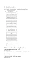
Installation Steps 

1) 

Plan the available space before installing the cabinet. You must reserve sufficient space for front and back doors for 
maintenance. 

2) 

Mount and fasten the cabinet at the designed location as planned. 

3) 

Install the appropriate cable management bracket and cables. 

4) 

Install the tray and wiring layer on the rack according to the configuration of one rack with one cabinet installed or 
one rack with multiple cabinets installed. 

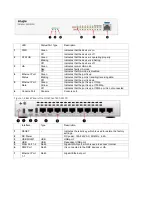
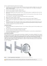
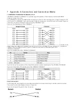
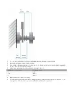
Guide Rails Installation 

Before installing a guide rail, you need to have some knowledge of standard 19-inch cabinets of IEC60297. The height of 
standard cabinets is measured in Rack Unit (RU, 1 RU = 44.45 mm (1.75 inch)). 1 RU is equal to the height of three holes 
(see Figure 3-1). The hole in the middle is an auxiliary installation hole, and the other holes are standard installation holes. 
Note that the space between neighboring standard installation holes is a little smaller than that between an auxiliary 
installation hole and its neighboring standard installation hole. When installing a guide rail for the RG-WALL1600-S3100 
series, ensure that the plane to carry the chassis should be installed on the plane of delimiters (entire-U delimiter) of the 
two neighboring RUs, as shown in Figure 3-1. 

Figure 3-1 Guide Rail   


Note: 

1 and 2 representing 1 RU delimiters 


Before installing a guide rail, confirm that the weight capacity of the guide rail meets requirements. 

Summary of Contents for RG-WALL1600-S3100

Page 1: ...RG WALL1600 S3100 Next Generation Firewall Hardware Installation and Reference Guide V1 3...

Page 2: ...or by any means without the prior written consent of Ruijie Networks is prohibited Exemption Statement This document is provided as is The contents of this document are subject to change without any n...

Page 3: ...s and concepts Obtaining Technical Assistance Ruijie Networks Website https www ruijienetworks com Technical Support Website https ruijienetworks com support Case Portal http caseportal ruijienetworks...

Page 4: ...148mm x 216mm x 38mm desktop AC Power 100 VAC to 240 VAC 50 60 Hz Maximum Current 110 V 1 5 A 220 V 0 75 A Power Consumption Average Max 11 7 14 W Heat Dissipation 40 BTU h The RG WALL1600 S3100 is an...

Page 5: ...data Off Indicates that the port is down 5 Ethernet Port Rate Green Indicates that the port is up at 1Gbp Yellow Indicates that the port is up at 100Mbp Off Indicates that the port is up at 10Mbp or...

Page 6: ...room before installation First cut off the power supply in case of an accident Be sure to make a careful check before you shut down the power supply Do not place the equipment in a damp wet location D...

Page 7: ...to bear the weight of the RG WALL1600 S3100 and its installation accessories Be sure that the dimensions of the cabinet is appropriate for installation of the RG WALL1600 S3100 that can reserve a cer...

Page 8: ...he grounding conditions on the installation site according to the grounding requirements and perform grounding properly as needed Safety Grounding The equipment using AC power supply must be grounded...

Page 9: ...tools Cross screwdriver straight screwdriver related electric and optical cables Bolts diagonal pliers straps Special purpose tools Anti static tool anti static glove stripping pliers crimping pliers...

Page 10: ...an and arrange the installation location networking mode power supply and wiring before installation Verify the following before installation The installation location is of a good air flow The instal...

Page 11: ...als from entering the cabinet Antistatic wrist straps should be provided in the cabinet Installation Steps 1 Plan the available space before installing the cabinet You must reserve sufficient space fo...

Page 12: ...t 3 Fasten the RG WALL1600 S3100 onto the cabinet with screws There are fastening notches on both the sides of the front panel on the equipment frame Use screws to fasten them to the fastening bracket...

Page 13: ...rs and twisted pairs to the cable management bracket 3 For the power cables you should bind them closely along the bottom of the chassis in a straight line wherever possible 3 8 Installation Verificat...

Page 14: ...browser The user name is admin and the password is firewall Configuring the Console Port and Establishing the Configuration Environment Connect the PC to the console port of the device through the Con...

Page 15: ...n in Figure 4 2 In the Connect Using field select the serial port you want to use Figure 4 2 4 After selecting the serial port click OK The Serial Port Parameter Setting window is displayed as shown i...

Page 16: ...ort of the device and the USB port of the PC properly Step 2 Right click My Computer and click Management Choose Device Manager Port COM and LPT and the COM port number will be displayed Step 3 Set te...

Page 17: ...xt and the following interface will be displayed Figure 4 6 3 After configuring the parameters click Next and you can configure the session name Click OK and the following interface will be displayed...

Page 18: ...e device is properly grounded The power cable is correctly connected The power supply voltage complies with the requirement of the device The console cable is correctly connected the terminal can be a...

Page 19: ...ower on you are recommended to perform the following checks to ensure the normal operation of follow up configurations Check that information appears on the terminal Check that the device indicator is...

Page 20: ...4 Ethernet Port Status Green Indicates that the port is up Blinking Indicates that the port is transiting receiving data Off Indicates that the port is down 5 Ethernet Port Rate Green Indicates that...

Page 21: ...hooting Procedures Fault 1 The system login password is lost Fault Description The login password is forgotten or lost and so it is not possible to configure the data Troubleshooting Please contact Ru...

Page 22: ...formation is displayed on the console Troubleshooting Check whether serial port cables are connected correctly and whether the connected serial port is identical with that configured on the super term...

Page 23: ...pairs of the 1000BASE T In addition to the above cables the 100BASE TX 10BASE T can also use up to 100m of 10Mbps 100 ohm Category 3 4 5 cables and 100Mbps 100 ohm Category 5 cables Figure A 2 shows t...

Page 24: ...s type of cables that often bend or suffer removal insertion should be greater than 10 times its diameter Requirement for the minimum fiber bend radius The diameter of a fiber tray to hold fibers cann...

Page 25: ...ect device running or cause device damage or cable damage during commissioning 220V and 48V power cords cannot be bundled on the guide rails of moving parts The power cables connecting moving parts su...

Page 26: ...bunches with cables in cable bunches clean and straight Binding by using buckles should be performed according to Table B 1 Cable Bunch Diameter mm Binding space mm 10 80 150 10 30 150 200 30 200 300...

Reviews: