·
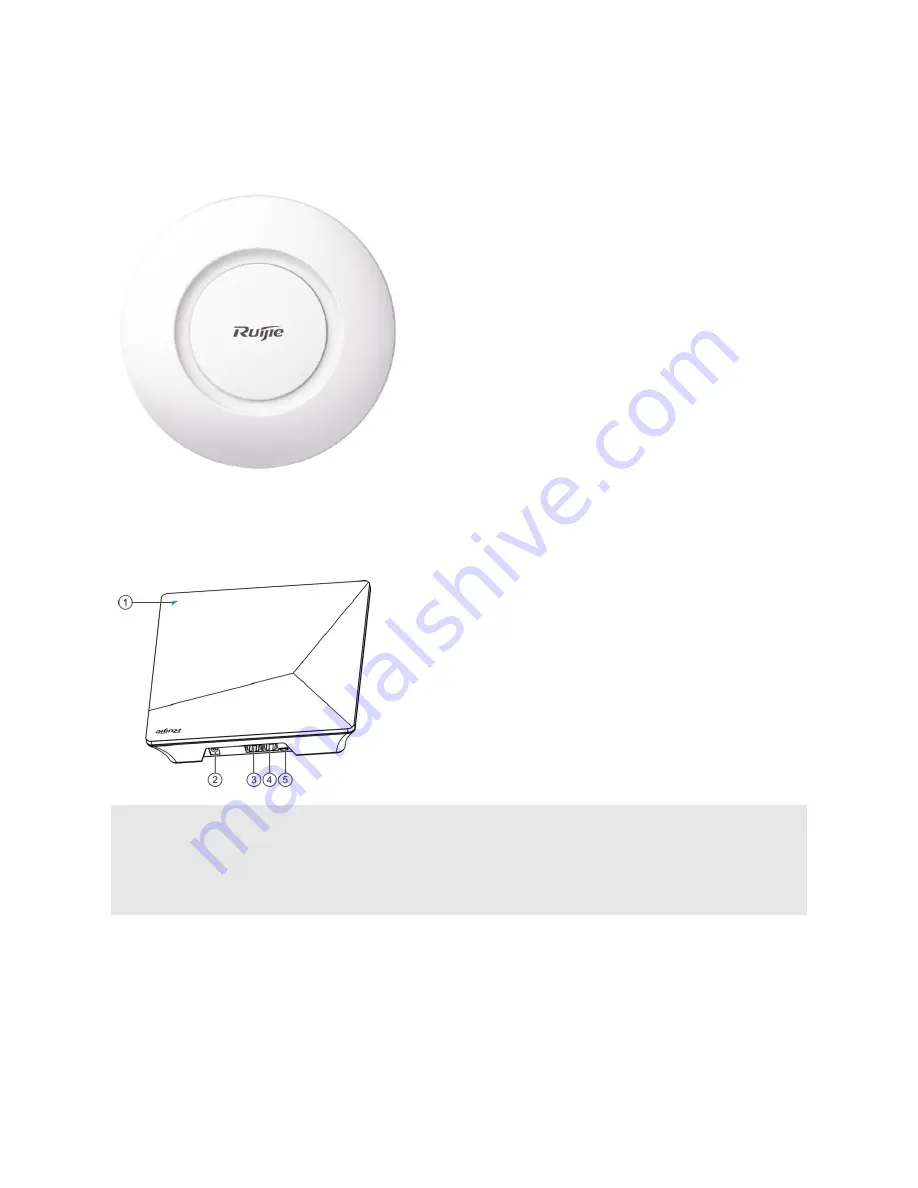
Product Image
Figure 1-1 Appearance of RG-MAP552(SR)
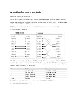
The device is powered up via the RG-AP520-I(G2). Connect one end of the cable to the uplink port and the other end to
the LAN2 port on RG-AP520-I(G2)., which is shown in the figure 1-2.
Figure 1-2 AP520-I(G2) port
Note
①
Indicator
②
48V DC power port
③
Console port
④
LAN2 port
⑤
USB port
LED Indicators
The LED indicator is near the WAN port
and works after you power on the device.
You can also turn off/on the LED indicator through the CLI command.


