background image

·


Summary of Contents for RG-MAP552(SR) series

Page 1: ...RG MAP552 SR Series Access Point Hardware Installation and Reference Guide V1 0 ...

Page 2: ...en consent of Ruijie Networks is prohibited are registered trademarks of Ruijie Networks Counterfeit is strictly prohibited Exemption statement This document is provided as is The contents of this document are subject to change without any notice Please obtain the latest information through the Ruijie Networks website Ruijie Networks endeavors to ensure content accuracy and will not shoulder any r...

Page 3: ...p www ruijienetworks com service aspx Technical Support Hotline 86 4008 111 000 Related Documents Documents Description Configuration Guide Describes network protocols and related mechanisms that supported by the product with configuration examples Command Reference Describes the related configuration commands including command modes parameter descriptions usage guides and related examples Documen...

Page 4: ...ry in which the AP is installed Spatial Streams 2 Max Throughput 802 11n up to 300Mbps 802 11ac up to 867Mbps Up to 1167Mbps per AP Modulation Types OFDM BPSK 6 9Mbps QPSK 12 18Mbps 16 QAM 24Mbps 64 QAM 48 54Mbps DSSS DBPSK 1Mbps DQPSK 2Mbps and CCK 5 5 11Mbps MIMO OFDM BPSK QPSK 16QAM 64QAM and 256QAM Max Tx Power 2 4G 15 dBm 5G 20 dBm Depending on the country of use laws and regulations Transmit...

Page 5: ...The AP can work in FIT mode only Physical Feature Dimensions ø138 mm x 35 mm diameter x height Height of AP only excluding mount kit Weight 0 385kg including mount kit Installation Wall ceiling mountable Service Ports 1 port 10 100 1000Base T uplink PoE Power Supply Via PoE IP Rating IP41 Environment Operating Temperature 10ºC to 45ºC Operating Humidity 5 to 95 RH non condensing Storage Temperatur...

Page 6: ... port and the other end to the LAN2 port on RG AP520 I G2 which is shown in the figure 1 2 Figure 1 2 AP520 I G2 port Note Indicator 48V DC power port Console port LAN2 port USB port LED Indicators The LED indicator is near the WAN port and works after you power on the device You can also turn off on the LED indicator through the CLI command ...

Page 7: ...indicates faults The AP is operational Continuous Blinking yellow 2 5Hz The AP is operational with device virtual management DVMG state error Blinking green 0 25Hz On for 2s and Off for 2s The AP is operational and at least one STA is associated with the AP Blinking green 0 25Hz Off for 3 8s and On for 0 2s The AP is operational but no STA is associated with the AP Continuous Blinking red 2 5Hz LE...

Page 8: ...ed according to network planning and features of communications equipment and considerations such as climate hydrology geology earthquake electric power and transportation Temperature and Humidity To ensure normal operation and service life of the device maintain appropriate temperature and humidity levels in your equipment room Operating Temperature 10ºC to 45ºC Storage Temperature 40ºC to 70ºC O...

Page 9: ...rically isolated unit Conducted interference results from the electromagnetic wire or signal cable connection between the source and the sensitive component along which cable the interference conducts from one unit to another Conducted interference often affects the power supply of the equipment but can be controlled by a filter Radiated interference may affect any signal path in the equipment and...

Page 10: ... Meter Multimeter The listed tools are customer supplied except wall anchors and screws ...

Page 11: ...have carefully read the requirements described in Chapter 2 Installation Flowchart Figure 3 1 Installation Flowchart Precautions To avoid damages to the AP observe the following safety precautions Do not power the device during installation Install the device in a well ventilated location Do not subject the device to high temperatures ...

Page 12: ...he AP is working Verify that the power supply matches the equipment power Fasten the device tightly Installation Procedure 1 Drill holes on the wall and fasten the mount kit with screws 2 Align the holes at the back the AP with the hooks of the mount kit 3 Fasten the AP 4 Install the security lock Figure 3 1 RG MAP552 SR Installation Wall Anchors and Screws Wall anchors and screws are customer sup...

Page 13: ...P on a wall make sure the arrow on the mount kit points upward The square feet should fit easily into the mounting slots Do not forcibly push the AP into the slots After installation verify that the AP is securely fastened ...

Page 14: ...up via RG AP520 I G2 Powering up the AP Checking before power up Check if AP520 I G2 and RG MAP552 SR are properly connected Checking after power up After powering up it is recommended that you check the following to ensure normal operation of the AP Check if the LED keeps blinking green ...

Page 15: ... 8s and On for 0 2s 0 25Hz The AP is operational but no STA is associated with the AP Remote Maintenance RG MAP552 SR operates in Fit mode you can use AC to centrally manage and maintain the AP Removing AP It is recommended that you check the following items before removing the AP The AP is powered off The security lock is removed Make sure that the AP is removed from the mount kit properly The te...

Page 16: ...d on Verify that the cable is connected properly LED keeps blinking yellow The AP is operational with DVMG state error Wireless client cannot find the AP 1 Follow the abovementioned two steps 2 Verify that the AP is configured correctly 3 Move the client device to adjust the distance between the client and the AP ...

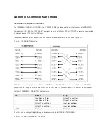
Page 17: ...igure A 1 1000BASE T Connection 10BASE T uses Category 3 4 5 100 ohm UTP STP and 1000BASE T uses Category 5 100 ohm UTP STP for connections Both support a maximum length of 100 meters Table A 1 shows100BASE TX 10BASE T pin assignments Table A 1 100BASE TX 10BASE T Pin Assignments Pin Socket Plug 1 Input Receive Data Output Transmit Data 2 Input Receive Data Output Transmit Data 3 Output Transmit D...

Page 18: ... ...

Page 19: ... ...

Reviews: