background image

25

Preparing the 7781CM at the Depot and Shipping to the Field

Operating the CM

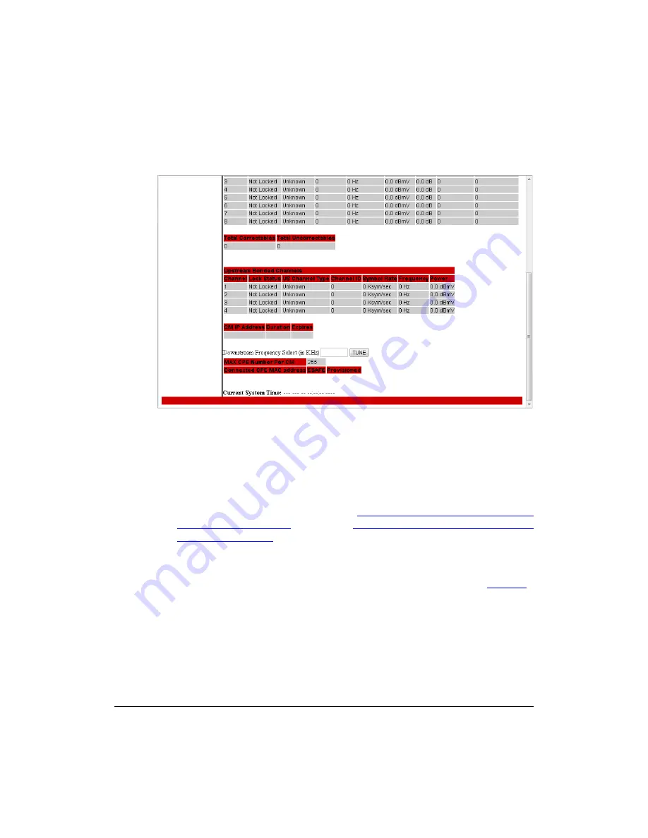
Figure 15.

Connection Status page - Page 2 of 2

Configuring the Downstream Frequency

The 

Connection Status 

page allows you to set the downstream frequency for the cable 

modem. Configuring the downstream frequency enables the device to quickly obtain a 
direct frequency lock with the CMTS upon bootup and helps to save several minutes of 
scanning for an available downstream frequency from the CMTS.

1.

Log into to the 

Status 

page as described in 

“Logging Into the CM Web Interface from 

the 7781CM Ethernet Port”

 on page 21 or 

“Logging Into the CM Web Interface using 

a Dynamic IP Address”

 on page 22.

2.

Click 

Connection

 on the menu on the left sidebar. The CM web interface displays the 

Connection Status

 page.

3.

Scroll down to the 

Downstream Frequency Select (in KHz) 

parameter. See 

Figure 15

.

4.

Enter the downstream frequency (in kiloHertz) that you want the cable modem to use 
to connect to the CMTS when it boots up. 

5.

Click 

TUNE

 to have the cable modem save your changes.

Summary of Contents for ZoneFlex series

Page 1: ...kus Wireless ZoneFlex 7781CM Dual Band 802 11n Strand Mount Outdoor Access Point with Integrated Cable Modem Installation Guide Part Number 800 70426 001 Rev B Published January 2013 www ruckuswireless com ...

Page 2: ......

Page 3: ...the GPS Antenna 12 Performing a Site Survey 14 3 Preparing the 7781CM at the Depot and Shipping to the Field 15 Unpacking the 7781CM 15 Package Contents 15 Finding the AP and CM MAC Addresses 17 Powering the 7781CM with DC 18 Preparing the Administrative Computer 19 Operating the CM 21 About the CM Command Line and Web Interfaces 21 Logging Into the CM Web Interface from the 7781CM Ethernet Port 2...

Page 4: ... 38 Restoring the Administrative Computer s Network Settings 39 Shipping the 7781CM to the Field 39 4 Installing the 7781CM in the Field 40 Installation Components and Constraints 40 Deploying the 7781CM 41 Mounting the 7781CM 41 Safety Cabling the 7781CM 41 Earth Grounding the 7781CM 42 Installing the Cable Power Tap 43 Powering the 7781CM with POC 44 Checking the Signal Level with an RF Power Me...

Page 5: ...SIS Compliant 7781CM 53 EuroDOCSIS Compliant 7781CM 53 Japan DOCSIS Compliant 7781CM 54 6 What to Do Next 55 Changing the Administrative Password 55 Configuring the Security Settings 55 Configuring Advanced Settings and Features 55 Reading Related Documentation 55 Appendix A Factory Supplied and Customer Ordered Parts 57 Appendix B Rebooting and Resetting the 7781CM 58 Rebooting and Resetting the ...

Page 6: ...iv ...

Page 7: ...nfiguring network equipment Consequently it assumes a basic working knowledge of local area networking cable modem setup and configuration wireless networking and wireless devices Figure 1 7781CM NOTE The AP part of the 7781CM can be managed using an AP web browser interface an AP command line interface CLI a simple network management protocol SNMP interface and Ruckus Wireless ZoneDirectorTM and ...

Page 8: ...th five main steps Each step includes some substeps Figure 2 shows the main steps and Table 1 includes the substeps Figure 2 Adding a 7781CM to an existing Ruckus Wireless network flowchart Planning the Installation Preparing at the Depot and Sending to the Field Installing in the Field Operating and Troubleshooting What to Do Next ...

Page 9: ... the Administrative Computer Operating the CM Using SSH to set the ZoneDirector IP address on the AP Configuring the AP for Management by FlexMaster or for Standalone Operation Verifying AP Operation Shipping the 7781CM to the Field 4 Installing the 7781CM in the Field Installation Components and Constraints Deploying the 7781CM Verifying AP and CM Operation 5 Operating and Troubleshooting the 778...

Page 10: ...ireless SmartMesh Root Access Point Related Documentation In addition to this guide each Cable Modem Access Point documentation set includes the following User Guide Provides detailed information on how to configure the functions of the unit The User Guide is available for download on the Ruckus Wireless Support Web site at http support ruckuswireless com documents Release Notes Provides late brea...

Page 11: ...ions You can email your comments to Ruckus Wireless at docs ruckuswireless com When contacting us please include the following information Document title Document part number on the cover page Page number if appropriate For example ZF7781CM Dual Band 802 11n Strand Mount Outdoor Access Point with Integrated Cable Modem Installation Guide Part number 800 70426 001 Rev B Page 49 ...

Page 12: ...odem ordering part number 901 7781 WW11 Japan DOCSIS 3 0 cable modem ordering part number 901 7781 JP21 The 7781CMs are best deployed where internal antenna lateral beamforming can provide the greatest reach and throughput to a wide coverage area and provide the greatest distance between APs in a connecting device See Figure 3 for internal antenna coverage patterns and see Figure 4 for a typical m...

Page 13: ...7 Planning the 7781CM Installation 7781CM Versions Figure 4 Typical mesh elevation plane coverage side view Excellent Reach Excellent Reach Excellent Reach 7781 CM RAP 7782 MAP ...

Page 14: ...ower to external devices PoE output and internal CM heater are only supported when the 7781CM receives Power Over Cable POC from the HFC cable plant Reset Button under blanking cap Referto AppendixB RebootingandResettingthe7781CM onpage 58 to access the reset button and either reboot the AP or reset the AP to factory defaults DC Connector under blanking cap In addition to the power supplied by the...

Page 15: ... purpose LEDs are used both by the CM part and the AP part of the 7781CM When the WHITE LED is lit the LEDs are in Cable Modem mode When the GREEN LED is lit the LEDs are in Access Point mode While the 7781CM is booting up the LEDs are in CM mode Once bootup is completed the LEDs alternate between CM and AP modes NOTE The 7781CM LEDs turn off after a while This is normal operation BLUE Far right G...

Page 16: ...flashes as CM tries to acquire downstream Red goes solid when downstream is acquired Blue flashes to indicate communication across the AP link 7 Yellow LED then comes on solid when upstream acquired 8 Middle Green on indicates cable modem on line successfully CM Online Steady State White on indicates CM mode Red yellow middle green and blue LEDs are on The LEDs now alternate between CM and AP mode...

Page 17: ...r State AP Standalone Mode AP ZoneDirector Mode Red Flashing 2 4GHz WLAN is up but no clients 2 4GHz WLAN is up but no clients Red Solid Atleastone2 4GHzwirelessclient isassociatedwiththeaccesspoint and signal strength is strong Atleastone2 4GHzwirelessclient isassociatedwiththeaccesspoint and signal strength is strong Yellow Solid Atleastone2 4GHzwirelessclient isassociatedwiththeaccesspoint and ...

Page 18: ...s powered by POC only When the 7781CM is powered by 12 VDC the heater is disabled Positioning the GPS Antenna The 7781CM AP includes an internal GPS antenna If the AP is to be used with the optional GPS feature enabled then the GPS antenna must be mounted outdoors and have as clear a view of the sky as possible as close as possible to 360 degrees and with no obstructing trees or buildings The GPS ...

Page 19: ...e 7781CM Installation Positioning the GPS Antenna Figure 7 GPS Antenna Location under 7781CM Radome Figure 8 7781CM Dome Down Mount GPS Antenna Position Connector End LED End Keep Sky View Clear Connector End LED End ...

Page 20: ... mounting the radio higher off of the ground with the AP oriented so that the dome is tilted down For recommended orientation examples refer to 7781CM Versions on page 6 Physical environment Clear or open areas provide better radio range than crowded or filled areas The less cluttered the operating environment the greater the wireless range Obstructions building materials and sources of interferen...

Page 21: ... 802 11n Outdoor Access Point with Integrated DOCSIS 3 0 Cable Modem Part number 901 7781 WW01 ZF7781CM Strand Mount Dual Band 802 11n Outdoor Access Point with Integrated EuroDOCSIS 3 0 Cable Modem 4 Verify that all items listed in Package Contents are included in the package Check each item for damage If any item is damaged or missing notify your authorized Ruckus Wireless sales representative N...

Page 22: ...npacking the 7781CM One loop and eye safety cable One M25 data cable gland One hard line F connector to RG11 cable adapter One green yellow earth ground wire with ring terminal One 12mm M6x1 earth ground screw with split lock and flat washers This Installation Guide ...

Page 23: ...e AP and CM MAC Addresses The 7781CM has separate MAC addresses for the internal AP and cable modem CM See Figure 9 for the location of the AP MAC address label See Figure 10 for the CM MAC address label location Figure 9 Access Point MAC address label location Figure 10 Cable Modem MAC address label location ...

Page 24: ...ure 11 CAUTION This product is intended to be supplied by a Listed Direct Plug In Power Unit marked Class 2 or LPS sub clause 2 5 of standard EN 60950 1 NOTE If you would rather use POC from HFC cable plant then refer to Powering the 7781CM with POC on page 44 Figure 11 Typical 7781CM customer supplied DC power supply 2 Remove the blanking cap covering the DC connector see Figure 5 3 Plug the DC p...

Page 25: ...e administrative computer 2 On your Windows 7 or Windows XP computer open the Network Connections or Network and Dial up Connections control panel according to how the Start menu is set up On Windows 7 click Start Control Panel Network and Sharing Center Change Adapter Settings On Windows XP click Start Control Panel Network Connections 3 When the Network Connections window appears right click the...

Page 26: ...K again to close the Local Area Connection Properties dialog box Windows saves the IP address settings that you have configured Table 5 Configure your computer s IP address settings IP address 192 168 100 22 or any address in the 192 168 100 x network except 192 168 100 1 which is the default IP address assigned to the CM or 192 168 100 2 which is the default IP address assigned to the AP Subnet m...

Page 27: ...odem Viewing the SNMP Event Log About the CM Command Line and Web Interfaces The CM command line interface is similar to the AP CLI and is used for CM specific operations You can perform most CM operating tasks from the CM web interface Logging Into the CM Web Interface from the 7781CM Ethernet Port 1 Collect required equipment and information An administrative computer as configured as described ...

Page 28: ...e computer start a Web browser 4 In the address bar enter the IP address that is assigned to the cable modem The cable modem web interface displays a login prompt 5 Leave User Name blank 6 In Password type ADMIN 7 Click Log In The Connection Status page appears indicating that you have successfully logged on to the cable modem web interface Continue with Viewing the Software Status Viewing the Sof...

Page 29: ...dard with which the device is compliant Hardware Version The version of the cable modem hardware Software Version The version of the cable modem software Cable Modem MAC Address The MAC address of the cable modem Cable Modem Serial Number The serial number of the cable modem CM Certificate Indicates whether a security certificate is installed Table 7 Status table Item Description System Up Time In...

Page 30: ...the IP address that is currently assigned to the cable modem 1 Log into to the Status page as described in Logging Into the CM Web Interface from the 7781CM Ethernet Port on page 21 or Logging Into the CM Web Interface using a Dynamic IP Address on page 22 2 Click Connection on the menu on the left sidebar The CM web interface displays the Connection Status page NOTE The Downstream Power indicated...

Page 31: ...ning for an available downstream frequency from the CMTS 1 Log into to the Status page as described in Logging Into the CM Web Interface from the 7781CM Ethernet Port on page 21 or Logging Into the CM Web Interface using a Dynamic IP Address on page 22 2 Click Connection on the menu on the left sidebar The CM web interface displays the Connection Status page 3 Scroll down to the Downstream Frequen...

Page 32: ...mmends that you change the login and or password as follows a Enter a new CM user ID in Password Change User ID b Enter a new CM user password in New Password c If you are changing the password then re enter the new CM user password in Re Enter New Password d Enter the existing before change CM user password in Current User ID Password 4 Enable firewall protection as follows Click the Firewall Pro...

Page 33: ...ent Log 1 Log into to the Status page as described in Logging Into the CM Web Interface from the 7781CM Ethernet Port on page 21 or Logging Into the CM Web Interface using a Dynamic IP Address on page 22 2 Click Event Log on the menu on the left sidebar The CM web interface displays the SNMP Event Log Status page 3 View the SNMP events in the SNMP event log Figure 17 SNMP Event Log Status page 4 I...

Page 34: ... cable to the administrative computer s Ethernet port and then connect the other end to the 7781CM s Ethernet port 3 Change the administrative computer s IP address to the same subnet as the 7781CM The AP s default IP address is 192 168 100 2 4 Start the Telnet or SSH client program on the administrative computer 5 Log onto to the AP via Telnet or SSH using the following logon details User names s...

Page 35: ...boot 8 Log on to the command prompt again and then enter the following command get director info The command prompt displays the IP address of the ZoneDirector device that is managing the 7781CM 9 Verify that this IP address is the same IP address that you set in Step 6 NOTE If the ZoneDirector is set to Enable Mesh it automatically assigns the 7781CM AP as a Root AP You have completed the setting...

Page 36: ... AP and the FlexMaster server to complete this procedure Logging Into the AP s Web Interface 1 Collect required equipment and information An administrative computer as configured as described in Preparing the Admin istrative Computer on page 19 One Cat5e or better Ethernet cable MAC address 12 alphanumeric digits from the outside of the AP case 2 Verify that the AP is powered on as described in Po...

Page 37: ...Common Wireless Settings Configuring Common Wireless Settings The settings on the Common tab are required to enable wireless devices to associate with the AP NOTE The AP has one 2 4GHz radio and one 5GHz radio The wireless settings for each radio need to be configured separately on the Web interface To configure the 2 4GHz radio settings click Configuration Radio 2 4G To configure the 5GHz radio s...

Page 38: ...02 11b g n for Configuration Radio 2 4G Common 5GHz 802 11a n for Configuration Radio 5G Common Channel SmartSelect Channel Width 20 MHz Country Code If you purchased the AP in the United States of America this value is fixed to United States at the factory and is not user configurable If you purchased the AP outside the United States of America verify that the value is set to your country or regi...

Page 39: ...ss page appears Figure 20 Figure 20 The Configuration Radio 2 4 Wireless 1 tab 2 In Wireless Availability click Enabled 3 In Broadcast SSID click Enabled 4 Clear the SSID box and then type a unique and descriptive name that you want to call this wireless network For example you can type Ruckus Wireless AP This SSID is the name that helps users identify this wireless network in their wireless netwo...

Page 40: ...l on page 34 If you are configuring the AP for standalone operation then continue with Verifying AP Operation on page 36 Setting the FlexMaster Server Address Optional When you have a FlexMaster server installed on the network and you intend to use FlexMaster to manage the AP you can set the FlexMaster server address at this point Before starting this procedure make sure you obtain the correct Fle...

Page 41: ...e host name or IP address of the FlexMaster server in the URL The following are examples of valid FlexMaster server URLs http flexmaster intune server https flexmaster intune server http 192 168 20 1 intune server https 192 168 20 1 intune server 5 Click Update Settings to save your changes You have completed setting the FlexMaster server address on the AP NOTE Instructions on how to verify that t...

Page 42: ... the 7781CM with DC on page 18 3 Connect one end of the ethernet cable to the ethernet port on the 7781CM 4 Connect the other end of the ethernet cable to the same Layer 2 subnet as the FlexMaster and or ZoneDirector The same Layer 2 subnet means that there should not be any router between the AP and ZoneDirector The AP can also connect to the network using wireless backhaul if it is part of a mes...

Page 43: ...puter on page 38 Checking the TR069 Status FlexMaster Management Only If you configured the AP to report to a FlexMaster server on the network Setting the FlexMaster Server Address Optional on page 34 then make sure you verify that the AP can successfully communicate with the FlexMaster server You can do this by checking the TR069 status on the AP s web interface 1 In the AP s web interface go to ...

Page 44: ...ive Computer 1 Disconnect the AP from the power source 2 Verify that all LEDs are off 3 Disconnect the Ethernet cable that runs to the AP s RJ 45 Ethernet Port from your administrative computer 4 Disconnect the Ethernet cable from the administrative computer s Ethernet port Continue with Restoring the Administrative Computer s Network Settings ...

Page 45: ...s XP click Start Control Panel Network Connections 2 When the Network Connections window appears right click the icon for Local Area Connection and then click Properties 3 When the Local Area Connection Properties dialog box appears select Internet Protocol TCP IP from the scrolling list and then click Properties The TCP IP Properties dialog box appears 4 Restore the computer s network settings by...

Page 46: ...ed to install replace or service this equipment The professional installer is responsible for the proper installation and configuration of this AP The AP installation must comply with local regulatory requirements especially with those regulating operation near military and or weather radar systems WARNING Installation of this equipment must comply with local and national electrical codes CAUTION ...

Page 47: ...CM assembly on a cable strand you need to secure the cable clamps that are attached to the strand interface to the cable strand 1 Slightly loosen the square nuts that fasten the two cable clamps to the strand interface enough for the strand support cable to fit into the cable clamps 2 Place the cable clamps on the strand support cable 3 Tighten the two square nuts to approximately 16 ft lbs to sec...

Page 48: ...The cable strand is usually earth grounded and mounting the 7781CM on the cable strand earth grounds the 7781CM chassis as well if this is the case skip this procedure and continue with Installing the Cable Power Tap If the cable strand is not earth grounded then continue with the following 1 The color coding of ground wires varies by region Before completing this step check your local wiring stan...

Page 49: ...ower and the RF signal Ruckus Wireless recommends installing a cable power tap Antronix MGT2000 SDPE tap or equivalent close to the 7781CM Refer to the manufacturer s instructions to mount the cable power tap on the coaxial cable Figure 24 shows a typical cable power tap and connection to the CM using an RG6 quad shield cable Figure 24 Cable Power Tap Connection to the 7781CM Cable Modem High Outp...

Page 50: ...wer on self test CM Boot Sequence a All LEDs blink for a few seconds b White stays solid on c Red yellow middle green and blue blink in sequence d Red yellow and middle green blink together for a few seconds e Blue goes solid when the link to the AP is established f Red LED flashes as CM tries to acquire downstream Red goes solid when downstream is acquired Blue flashes to indicate communication a...

Page 51: ...signal level to the 7781CM Continue with Verifying CM and AP Operation Continue with Connecting and Sealing the RJ 45 Cable Optional or Verifying CM and AP Operation as required Table 10 Connector B signal level specifications Downstream Upstream 12 to 16dBmV 64 QAM TDMA 1xUpstream Pmin to 57dBmV 32 QAM 64 QAM Pmin to 58dBmV 8 QAM 16 QAM Pmin to 58dBmV QPSK S CDMA 1xUpstream Pmin to 56dBmV all mod...

Page 52: ... Feed the end of the RJ 45 cable through the sealing nut rubber O ring clamping ring assembly and cable gland base as shown in Figure 25 Figure 25 RJ 45 waterproof cable gland P N 902 0183 0000 3 Remove the Ethernet Port blanking cap from the 7781CM See Figure 5 for cap location 4 Connect the RJ 45 cable to the ethernet port in the 7781CM 5 Hand tighten the cable gland base into the 7781CM chassis...

Page 53: ...s the 7781CM 3 On the administrative computer start a Web browser 4 In the address bar enter the IP address that is assigned to the cable modem The cable modem web interface displays a login prompt 5 Leave User Name blank 6 In Password type ADMIN 7 Click Log In The Status page appears 8 On the menu on the left sidebar click Connection The Connection Status page appears as shown in Figure 14 and Fi...

Page 54: ... to report to a FlexMaster server on the network make sure you verify that it can successfully communicate with the FlexMaster server You can do this by checking the TR069 status on the AP s Web interface through the CMTS 1 Log in to the AP s Web interface through the CMTS as described in Logging Into the AP s Web Interface via CMTS on page 48 2 Go to the Administration Management page 3 Scroll do...

Page 55: ... show the status of one or the other at a time either access point status only AP Mode or cable modem status only CM Mode When the access point boots up the LEDs are in CM Mode Once the bootup process is complete the LEDs alternate between CM Mode and AP Mode The LEDs are color coded to enable you to quickly identify the current LED mode When you see the far right green LED the LEDs are in AP Mode...

Page 56: ...owing modes 1 Cable Modem Click this option if you want the LEDs to stay in CM Mode until you switch them to another mode 3 Alternate between modes 1 and 2 at 30 second period then disabled after 60 minutes Click this option if you want the LEDs to switch to CM Mode as soon as you click Save and then alternate with AP Mode every 30 seconds 4 Click Save 5 Check the access point for a white LED This...

Page 57: ...ress of the 7781CM AP that you want to configure 6 Find the OID 1 3 6 1 4 1 25053 3 1 4 7 3 ruckusZF7781CMControlLED 7 Set the value to the following 1 ledPerCM 1 After you set the LEDs to CM Mode they stay in CM Mode until you switch them to another mode 8 Check the 7781CM for a white LED This indicates that the LEDs are now in CM Mode NOTE If you see a far right green LED this indicates that the...

Page 58: ...e following command cd n cd hal mac_address 1 The CLI displays the CM s MAC address Retrieving the CM s MAC Address using the AP CLI Use AP command line interface via the CMTS to retrieve the CM s MAC address 1 Obtain the IP address assigned to the AP You can obtain this information from the DHCP server at the CMTS 2 Connect an administrative computer to the same subnet as the 7781CM 3 On the admi...

Page 59: ...e center of the channel is an integer spaced by 6MHz first from 93MHz to 999MHz 152 channels 4 Scans the harmonically related carrier HRC channels which moves the channels 1 25MHz off the standard frequencies so the video carriers are all related by 6MHz from 91 75 to 997 5MHz 152 channels A complete frequency scan requires approximately 469 channel checks Since each channel takes about 0 6 second...

Page 60: ...ng 1 Looks at the last known good channel repeat this every 64 channel checks 2 Checks the sixteen last known frequencies repeat this every 32 channel checks 3 Scans generic channels where the center of the channel is an integer spaced by 250kHz first from 112 MHz to 858 25 MHz 2986 channels A complete frequency scan requires approximately 4526 channel checks and lasts approximately 45 minutes NOT...

Page 61: ...authorized users from entering your wireless network and accessing your computers and files Ruckus Wireless strongly recom mends enabling and configuring wireless security on the AP The AP supports several types of encryption and authentication methods to help prevent unauthorized access to your wireless network Configuring Advanced Settings and Features The AP has been configured for basic operat...

Page 62: ...56 What to Do Next Reading Related Documentation ...

Page 63: ...M kit Earth ground screw 12mm M6x1 phillips pan head screw with split lock and flat washer 1 set 7781CM kit Stainless steel Safety Cable Kit 902 0115 0000 Customer supplied 1 5A 12 VDC power supply with 2 5mm inner diameter 5 5mm outer diameter positive center plug 902 0169 xxyy where xx Country and yy Revision Customer supplied Cable power tap and connecting cable Customer supplied Antronix MGT20...

Page 64: ...usly configured Also note that resetting and or rebooting the AP and CM disrupts all wireless network communications through this device There are different ways to reboot or reset the AP and CM parts of the 7781CM Using the Reset Button Inside the AP Remotely Rebooting the AP Using the Reset Button Inside the AP You can reset the AP and CM to their factory default settings by pressing the reset b...

Page 65: ...ir factory default settings and or rebooting the AP and CM Remotely Rebooting the AP NOTE The AP part of the 7781CM can be remotely rebooted but Ruckus Wireless does not recommend that the CM be remotely rebooted as the AP communicates with the administrative computer through the CM NOTE Before starting this procedure you must first obtain the related MIBs from Ruckus Wireless Contact your authori...

Page 66: ... cable modem to reset the CM to factory default settings The procedure isthe same regardlesswhether you perform this operation from the AP or CM NOTE Before starting this procedure you must first obtain the related MIBs from Ruckus Wireless Contact your authorized Ruckus Wireless sales representative or Ruckus Wireless Support Visit http support ruckuswireless com contacts for Ruckus Wireless Supp...

Page 67: ...61 Appendix B Rebooting and Resetting the 7781CM ...

Page 68: ...Copyright 2006 2013 Ruckus Wireless Inc 350 West Java Dr Sunnyvale CA 94089 USA www ruckuswireless com ...

Reviews: