Copyright © 2013 Ruckus Wireless, Inc.
Published July 2013, Part Number 800-70544-001 Rev A
Page 2 of 2
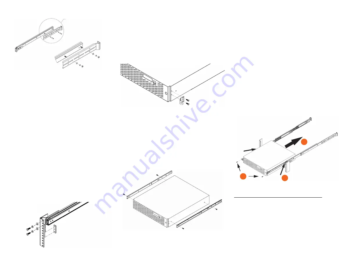
Figure 3: Attaching the rear brackets and outer rails
S
TEP
3: A
TTACH
THE
O
UTER
R
AIL
A
SSEMBLIES
TO
THE
R
ACK
P
OSTS
NOTE:
The two outer rail assemblies are interchangeable.
1
Locate an outer rail assembly in a vacant 2U space the rack
with the short bracket toward the front of the rack. If the
measurement in Step 2 was accurate, then the rail assembly
should fit exactly into the server rack.
NOTE:
Only use screws in the top and bottom holes of the front
brackets. Use three screws in the rear brackets.
2
Get a helper. If you are using factory-supplied fasteners, use
two factory-supplied screws and a bar nut (E and F in Figure
1) and loosely attach the front of the outer rail assemblies to
the front of rack (Figure 4). Use three factory-supplied
screws and a bar nut and loosely attach the rear of the outer
rail assemblies to the rear of rack.
If you are using customer-supplied fasteners, loosely attach
each end of the outer rail assemblies to the rack with five
customer-supplied fasteners, two on the front and three on
the rear.
NOTE:
Leave the outer rail assembly rack screws loose for now.
You will tighten them after the SCG or ZD chassis is positioned
in the rack.
3
Once you have verified the rail assembly length, tighten the
two screw sets holding the outer rail assemblies together.
Figure 4: Installing the customer-supplied screws and a bar nut
S
TEP
4: A
TTACH
THE
F
RONT
L
OCKING
B
RACKETS
TO
THE
S
ERVER
1
Remove the two front locking brackets (D in Figure 1) and
four #8-32 1/4” pan head screws (H in Figure 1) from the
package.
2
Attach one locking bracket to the side of the server as
shown.
3
Repeat for the other locking bracket.
Figure 5: Attaching a locking bracket
S
TEP
5: A
TTACH
THE
I
NNER
R
AILS
TO
THE
S
ERVER
1
Attach one inner rail (B in Figure 1) to the side of the server
chassis, making sure that the narrow end points toward the
rear of the chassis.
2
Secure the inner rail to the chassis using two #8-32 1/4” pan
head screws (H in Figure 1).
3
Repeat these steps for the other side of the chassis, making
sure that the narrow end of the inner rail points toward the
rear.
Figure 6: Attaching the inner rails
S
TEP
6: S
LIDE
THE
I
NNER
R
AILS
INTO
THE
O
UTER
R
AILS
AND
S
ECURE
TO
THE
R
ACK
WARNING:
The ZD and SCG servers are heavy (40 lbs/18.14kg).
Two people should work together to lift and slide the server into
the rack. Ruckus strongly recommends against one person
attempting to perform this task alone.
1
Align the inner rails (attached to the server chassis) with the
outer rail assemblies (loosely attached to the rack).
2
Engage the matching rails, and then slide the server chassis
into the rack until the two spring safety locks snap into
position.
3
Press down the two spring safety locks (one on each side).
See 1 in Figure 7.
4
Slide the server chassis all the way into the rack. Make sure
that the rail assemblies slide smoothly. See 2 in Figure 7.
5
Align the rail assemblies and tighten the screws holding the
rail assemblies to the rack posts.
6
Use two customer-supplied rack screws to secure the chassis
and front locking brackets into the rack. See 3 in Figure 7.
Figure 7: Securing the server to the rack
NOTE:
If necessary, make the front of the server flush with the
rack: (1) Remove the server and inner rails from the rack. (2)
Leave the front and rear brackets attached to the rack. Loosen
the screws holding the two outer rails to the front and rear
brackets (A and C in Figure 1). (3) Move the two outer rails back
in the rack as required. (4) Tighten the screws holding the two
outer rails to the front and rear brackets. (5) Replace the server
and inner rails in the rack (Figure 7).
Congratulations! You have completed mounting the
ZoneDirector 5000 or SCG 200 into your server rack.
Inset
1
3
2


