English
Tel. +49 7930 9211-0 Fax +49 7930 9211-150
18
The control unit has an integrated time switch. This can be used to control the time your unit will
come on, individually for each day of the week.
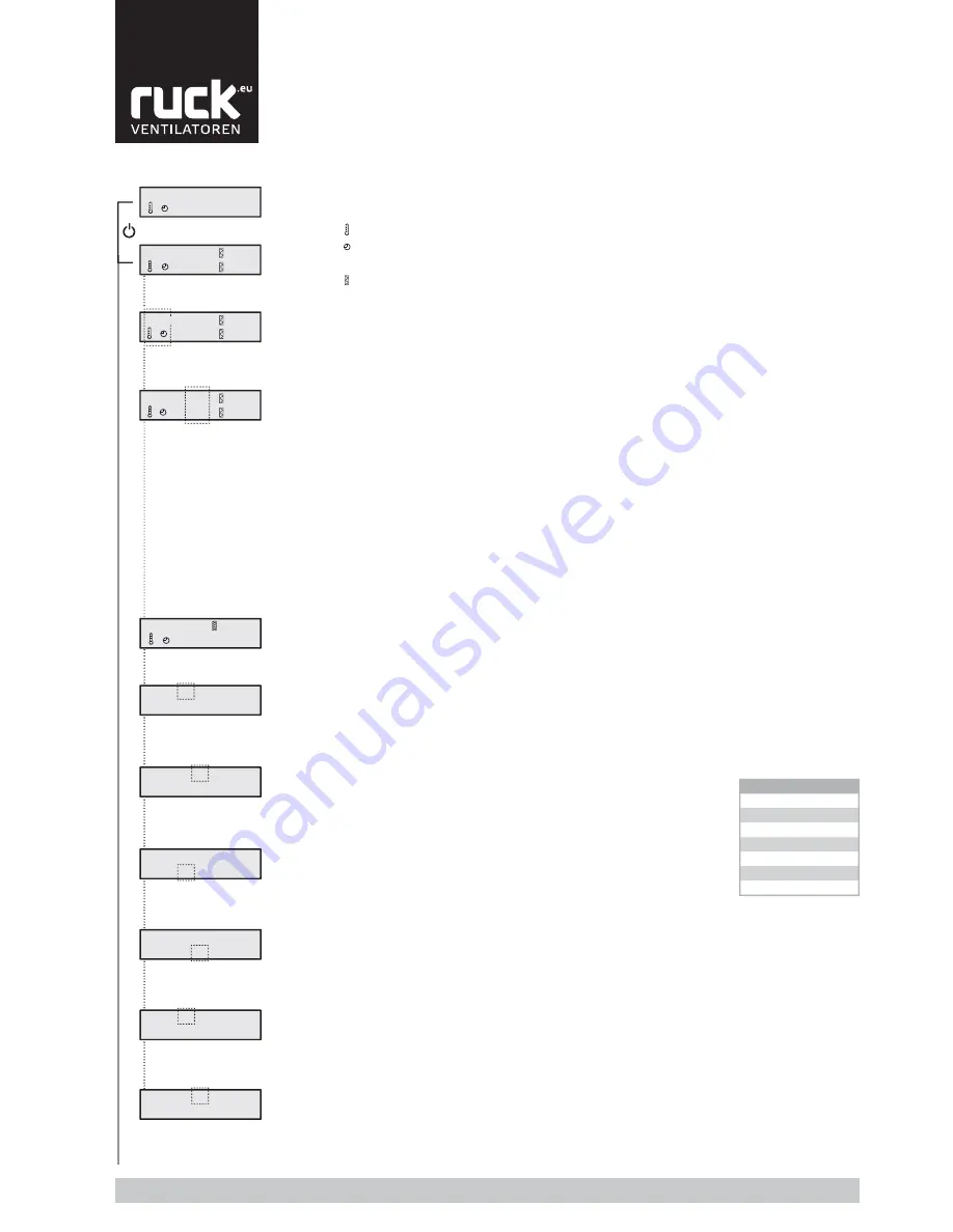
Setting the time switch
With the setting parameters for the time switch, the times when the unit is to come on (ON) or off
(OFF) can be set individually for each day of the week.
From the status display, press button
A
▲
and
B
▲
to get to the menu for setting the time switch.
1
5
:30
ON
DAY 18:30
OFF
1
5:
30
ON
DAY 18:30
OFF
1
5:30
ON
DAY
18
:30
OFF
1
5:30
ON
DAY 18:
30
OFF
2
6
:30
ON
DAY 19:30
OFF
2
6:
30
ON
DAY 19:30
OFF
21,0
1 0 %
8
A
B
B
A
B
A
B
A
B
A
B
A
Set
Day
1
Monday
2
Tuesday
3
Wednesday
4
Thursday
5
Friday
6
Saturday
7
Sunday
Table 3
On the display, on the top line, the display
fl
ashes for the „hour“ in which
the unit is to come on (ON) on day 1. Press buttons
B
(
▲
and
▼
) to set
the „hour“ and then con
fi
rm the entry with button
A
▲
.
The display then moves on to the „minutes“ which can be set in the same
way with buttons
B
(
▲
and
▼
) and con
fi
rmed with button
A
▲
.
(The minutes are set in 5-minute increments.)
On the display, on the bottom line, the display now
fl
ashes for the „hour“
in which the unit is to switch off on day 1. The „hour“ and „minutes“ are
again set and con
fi
rmed with buttons
B
(
▲
and
▼
) and button
A
▲
.
Once the entry has been con
fi
rmed, the display moves on to day 2 where the individual on and off
times can be set. Days 3 to 7 then follow.
Once you have set all of the parameters / days, press the „Mode button“ (
M
) to go back to the
unit‘s status display.
However, you do not have to go through the whole time switch menu to get back to the status
display. You can press the „Mode button“ (
M
) at any time to go back to the status display.
Note:
•
If the time 0:00 is given in the parameters, the unit will not switch on or off.
If, for example, you do not want the unit to come on at the weekend, you should set the value
to 0:00 for „Day 6“ and „Day 7“.
•
The values set are saved even when there is a power failure or if the battery in the control unit
runs down. Only the current time and day of the week have to be reset.
Note: Instructions on changing the clock battery are give in section 10.3.4.
9.3. Menu functions
•
Continuous mode
In continuous mode, the fan stages can be selected with buttons
B
(
▲
and
▼
) on the control unit.
The control system does not then affect the speed of the fan (except for in the case of a fault). Con-
tinuous mode can been seen by the constant display of the fan stage on the display.
•
Automatic mode
In automatic mode the fan will always try to run in the highest possible stage.
If the set-point temperature set is not achieved by this, it switches to a lower fan stage to be able
to ensure a constant room and exhaust air temperature.
8
Switching the unit on/off on the control unit.
Press the ON/OFF button (1) to switch the unit on or off.
The unit‘s status now appears on the display with the current values.
»
Set-point temperature display
»
Time switch
»
Fan stage
»
Filter, degree of contamination
Changing the set-point temperature
When commissioning for the
fi
rst time, a set-point value of 21°C is given. This value is shown on the
left-hand side of the display. The set-point value can be increased (
▲
) or reduced (
▼
) on the control
unit using buttons
A
.
(The setting range is limited by parameters P 1 and P 2.)
Changing fan stage
There are two possibilities for selecting the fan stages: automatic and continuous mode.
Press buttons
B
(
▲
and
▼
) at the same time to switch between the two modes. Automatic mode is
indicated on the display by the regular
fl
ashing of the fan stage selected.
9.3.1. Time / Time switch
21,0°
1
0%
8
4%
21,0°
2
0%
8
4%
OFF
8
21,0°
1
0%
8
4%
A
B
Summary of Contents for RLI 1200 EC
Page 31: ...English www ruck eu 31 15 2 Wiring diagrams RLI 700 FC Wiring diagrams No 119820 Part 1...
Page 35: ...English www ruck eu 35 RLI 700 EC Wiring diagrams No 123344 Part 2...
Page 36: ...English Tel 49 7930 9211 0 Fax 49 7930 9211 150 36 RLI 900 FC Wiring diagrams No 118155 Part 1...
Page 39: ...English www ruck eu 39 RLI 1200 FC Wiring diagrams No 119819 Part 1...
Page 45: ...English www ruck eu 45 RLI 1600 FC Wiring diagrams No 120619 Part 1...
Page 51: ...English www ruck eu 51 RLI 2000 FC Wiring diagrams No 120625 Part 1...
Page 57: ...English www ruck eu 57 Notes...


