RTS MKP-4 User Instructions Download Page 12

2.4

CONNECTIONS

2.4.1

Mic Connector

To connect a panel microphone, such as the RTS model
MCP5 or MCP6, screw the microphone into the Mic
connector on the front panel of the MKP-4.

For Mic connector specifications, see page

8

.

2.4.2

Headset Connector

The Headset connector accepts a monaural, dy-
namic-microphone headset (headphones and micro-
phone). If you use a headset, make sure DIP switch 4 is
set to the Open position (page

9

).

Alternatively, headphones can be connected when a panel
microphone is used for talkback. Or, a handheld dynamic
microphone can be connected when a speaker is used for
listening.  If you use either of these special configura-
tions, make sure DIP switch 4 is set to the Close position
(page

9

).

For Headset connector specifications, see page

8

.

2.4.3

Speaker Connector

The speaker output can be used for listening when a panel
microphone is used for talkback.  If you use this configu-
ration, make sure DIP switch 4 is set to the Open position
(page

9

).

The speaker output can also be used for listening when a
handheld microphone is used for talkback. If you use this
special configuration, make sure DIP switch 4 is set to the
Close position (page

9

).

For Speaker connector specifications, see page

8

.

2.4.4

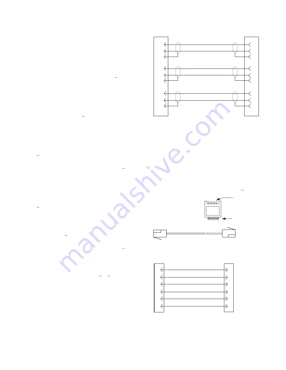
Connection To Intercom System

Use a standard RTS intercom cable. Either a 9-pin or
RJ12 type can be used. Refer to Figure

3

or

4

. Plug one

end of the cable into the appropriate Frame connector on
the back panel of the keypanel. Plug the other end into the
appropriate port of the intercom system. (This will be the
port number that you designated previously when setting
the Address switch.)

Keypanels may be connected while the intercom
system is running.

Note that 9-pin intercom cables for use with an
ADAM CS frame must use special connectors at the
intercom matrix end as described in Figure

3

.

12 User Instructions MKP-4 Keypanel

DE-9P (MALE)

TO KEYPANEL

DE-9S (FEMALE)

TO INTERCOM SYSTEM*

CABLE TYPE:
BELDEN 8777

1

2

6

4

5

9

7

8
3

1

2

6

4

5
9

7

8

3

DATA

AUDIO TO MATRIX

AUDIO FROM MATRIX

+

-

+

-

-

+

When connecting to an ADAM CS back panel, use
only low-profile cable connectors such as AMP
Part No. 747516-3 (Telex Part No. 59926-678)

IMPORTANT!

*

Figure 3. 9-pin Intercom cable wiring diagram.
Important: Shield connections at keypanel end are
optional and may cause ground loops if used.

3 TWISTED PAIR TELEPHONE CABLE

1

2

3

4

5

6

DATA  -

1

2

3

4

5

6

AUDIO FROM

AUDIO TO MATRIX -

DATA  +

123456

CONTACTS

LATCH

RJ12 MODULAR PLUG

AMP 5-555042-3 or equivalent

(View from cable entrance)

Use AMP Chordal
Crimp Tool 231648-1
or equivalent

PAIR 1: AUDIO TO MATRIX
PAIR 2: AUDIO FROM MATRIX
PAIR 3: DATA

AUDIO FROM MATRIX -

AUDIO TO

Figure 4. RJ12 Intercom cable wiring diagram

Summary of Contents for MKP-4

Page 1: ...9350 7647 000 Rev A 5 99 USER INSTRUCTIONS MKP 4 KEYPANEL ADAM ADAM CS AND ZEUS INTERCOM SYSTEMS Copy Headset Volume Mic Headset Call Waiting MKP 4 Listen Clear Talk MKP 4 Keypanel...

Page 2: ...en with respect to RTS products It is the responsibility of the user to determine before purchase that this product is suitable for the user s intended purpose ANY AND ALL IMPLIED WARRANTIES INCLUDING...

Page 3: ...ch it was installed 2 Restrictions a You may not market distribute or transfer copies of the Software to others or electronically transfer or duplicate the Software YOU MAY NOT REVERSE ENGINEER DECOMP...

Page 4: ...4 User Instructions MKP 4 Keypanel This page intentionally left blank...

Page 5: ...OPERATIONAL CHECK 13 KEYPANEL SETUP 13 ASSIGNING INTERCOM KEYS 13 CLEARING KEY ASSIGNMENTS 14 PRINTING DESIGNATION STRIPS 14 CHANGING SETUP PAGES 14 OPERATION 15 HEADSET BUTTON OPERATION 15 DIP switch...

Page 6: ...iagram 12 Figure 4 RJ12 Intercom cable wiring diagram 12 Figure 5 Scroll Copy and Clear Buttons 13 Figure 6 Call Waiting Window and Key 13 LIST OF TABLES Table 1 Address number vs intercom port number...

Page 7: ...LED indicators for each key Provide indications for talk on off listen on off incoming call busy for keys assigned to talk to IFB s and in use for keys as signed to talk to either IFB s or ISO s 3 Des...

Page 8: ...8 port Audio I O cards Only positions 1 C are used for ADAM intercom systems with 12 port Au dio I O cards The remaining switch positions are not used 1 5 SPECIFICATIONS Matrix Input Output 8 dBu nom...

Page 9: ...next to that key will flash The flash can be set for 15 second timeout or until the caller s talk key is released DIP Switch 3 Open Default setting TIF 951 operation enabled Close MKP 4 cannot answer...

Page 10: ...ack of the ADAM CS frame that the keypanel will be connected to look up that connector number in the worksheet then read across to the appropriate logical keypanel number Use that number to set the MK...

Page 11: ...onfiguration Using an MCP1 Rack Mount Kit Single unit Rack Mount Configuration Using an MCP2 Rack Mount Kit Tandem Configuration Using an MCP4 Tandem Mount Kit Console Mount Configuration Using an MCP...

Page 12: ...rcom System Use a standard RTS intercom cable Either a 9 pin or RJ12 type can be used Refer to Figure 3 or 4 Plug one end of the cable into the appropriate Frame connector on the back panel of the key...

Page 13: ...EUSedit or ADAMedit Assign intercom keys at the MKP 4 as follows 1 Make sure the key that you want to assign is off 2 Press the Scroll Up or Scroll Down key to view the list of intercom names in the c...

Page 14: ...play Dashes should display 3 Press and hold the Copy button then tap the intercom key that you want to clear Tap up to clear the listen assignment Tap down to clear the talk assignment The talk or lis...

Page 15: ...tly assigned The electronic latching feature DIP switch 5 must be enabled in order to use latching See page 9 for details 4 3 2 Intercom Key Operation for Different Types of Key Assignments Basic Talk...

Page 16: ...previously described the talk indicator for a key will flash when there is an incoming call to that key and you may activate that key to talk back Also if DIP switch 1 page 9 was set to the Open posit...

Page 17: ...follows 1 Make sure the Call Waiting window is clear Dashes should display If not press upward on the Call Waiting key 2 Hold down the Call Waiting key 3 While holding down the Call Waiting key tap t...

Page 18: ...84 392 400 Cards 51 75 51 52 53 54 55 56 57 58 59 60 61 62 63 64 65 66 67 68 69 70 71 72 73 74 75 1 401 409 417 425 433 441 449 457 465 473 481 489 497 505 513 521 529 537 545 553 561 569 577 585 593...

Page 19: ...204 216 228 240 252 264 276 288 300 Cards 26 50 26 27 28 29 30 31 32 33 34 35 36 37 38 39 40 41 42 43 44 45 46 47 48 49 50 1 301 313 325 337 349 361 373 385 397 409 421 433 445 457 469 481 493 505 517...

Page 20: ......

Reviews: