


rector or producer to give instructions to a listener, such
as a news anchor during a television broadcast) could ac-
cidentally be left on, causing confusion for the IFB lis-
tener. To prevent such accidents, the latching feature can
be turned off.
DIP Switches 6-8
Not used. Leave Open.
2.2.2
Address Switch
☞
In Zeus, ADAM CS, and ADAM intercom systems,
intercom ports are arranged in groups of 8 or 12
intercom ports. Within each group, each MKP-4
keypanel is uniquely identified by its Address switch
setting.
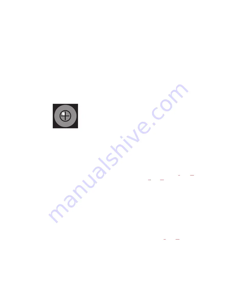
The Address switch has a white pointer which points to
the current switch setting. Determine the proper setting as
follows:
Important! Always reset the keypanel after changing the
Address switch setting. Do this by briefly removing
power to the keypanel.
Zeus Intercom Systems: Intercom port connectors on the
Zeus back panel are arranged in three groups of eight in-
tercom ports. For each group, intercom port connectors
are labeled ID 1, ID 2, etc. When you connect an MKP-4
keypanel to Zeus, set the MKP-4 Address switch to match
the corresponding ID number on the Zeus back panel.
Note that address switch settings 0, and 9 through F are
not used.
ADAM CS Intercom Systems: Each Audio I/O card
contains 1 group of 8 intercom ports. However, the
method of breaking out the groups depends on the type of
connectors on the back panel. To determine the MKP-4
Address switch setting, use the planning worksheets in the
ADAM CS Installation Manual. These are located near
the back of the Installation Manual:
•
ADAM CS with RJ12 or DB-9 back panel: You
can determine the keypanel address from the
worksheets in either of two ways: 1) If you know the
port number that a keypanel will be connected to,
look up the port number in the worksheet, then read
across to the appropriate logical keypanel number for
that port number. Use that number to set the MKP-4
Address switch. 2) If you know the connector number
(on the back of the ADAM CS frame) that the
keypanel will be connected to, look up that connector
number in the worksheet, then read across to the
appropriate logical keypanel number. Use that
number to set the MKP-4 Address switch. Note that
address switch settings 0, and 9 through F are not
used.
•
ADAM CS frame with 50-pin Telco back panel:
You can determine the keypanel address from the
worksheet in either of two ways: 1) If you know the
port number that a keypanel will be connected to,
look up the port number in the worksheet, then read
across to the appropriate logical keypanel number for
that port number. Use that number to set the MKP-4
Address switch. 2) If you know the connector
numbers and pin numbers that the keypanel will be
connected to, look up these numbers in the
worksheet, then read across to the appropriate logical
keypanel number. Use that number to set the MKP-4
Address switch. Note that address switch settings 0,
and 9 through F are not used.
ADAM Intercom Systems: Each Audio I/O contains 1
group of either 8 or 12 intercom ports per card. However,
the individual intercom ports may be broken out using
various types of breakout panels or punch blocks, and
groups may not be easily identified. It may be easier to set
the MKP-4 Address switch using the actual intercom port
numbers. To do this, refer to Table
(for 8-port
cards) or Table
, page
(for 12-port cards). Locate the
intercom port number to which the MKP-4 will be con-
nected. Then, read across to the “Address” column to find
the Address number. Set the MKP-4 Address switch to
this number. Note: settings 0, and 9 through F are not
used with 8-port cards settings 0, and C through F are not
used with 12-port cards.
2.3
MOUNTING THE MKP-4
The MKP-4 can be used on a desktop, or con-
sole-mounted, or rack-mounted. Some possible mounting
configurations and the required optional mounting hard-
ware are shown in Figure
MKP-4, always allow adequate room behind the unit for
cable access. There are no special ventilation require-
ments.
10 User Instructions MKP-4 Keypanel
01
2
3
4
5
6
7 8
9 A B
C
D
E
F


