


It’s Under Control
®
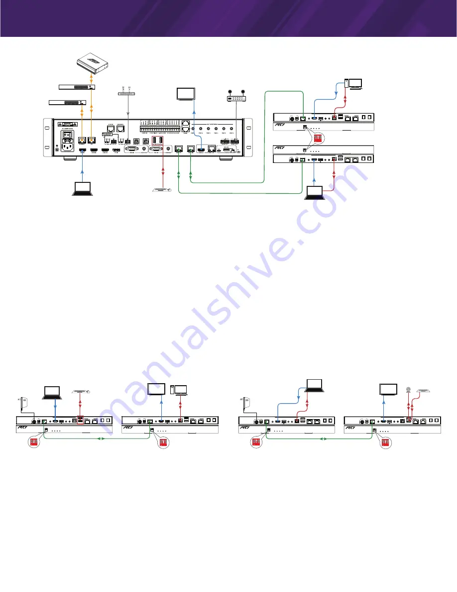
VXP-T Installed with VXP-82
SET
POWER STATUS HDCP
LINK
Model VXP-T
HDBaseT Extender-Transmitter
RS232
HDBT OUT
AUDIO IN
HDMI IN
IR IN
IR OUT
USB-HOST
USB-DEVICE
S/PDIF IN
S/PDIF OUT
DC 12V
TX
RX
ETHERNET
RS232
HDBT OUT
AUDIO IN
HDMI IN
IR IN
IR OUT
USB-HOST
USB-DEVICE
S/PDIF IN
S/PDIF OUT
DC 12V
TX
RX
ETHERNET
SET
POWER STATUS HDCP
LINK
Model VXP-T
HDBaseT Extender-Transmitter
Ethernet Switch
Ethernet Switch
Wireless MIC
Receiver
Display
HDMI OUT
HDMI IN
HDMI
Ethernet
Ethernet
Laptop
Laptop
Keyboard & Mouse
USB
DEVICE
USB
HOST
Audio In
CAT-x
CAT-x
1 2 3
ON
Set DIP Switch #2 on
Front of VXP-T "UP"
HDMI
PC
VXP-T
HDBaseT
Transmitter
Amplifier
VXP-82
VXP-T
HDBaseT
Transmitter
Control System
USB
HOST
SET
POWER STATUS HDCP
LINK
Model VXP-R
HDBaseT Extender-Receiver
RS232
HDBT IN
HDMI OUT
IR IN
IR OUT
S/PDIF IN
S/PDIF OUT
DC 12V
TX
RX
ETHERNET
AUDIO OUT
USB-HOST
USB-DEVICE
SET
POWER STATUS HDCP
LINK
Model VXP-T
HDBaseT Extender-Transmitter
RS232
HDBT OUT
AUDIO IN
HDMI IN
IR IN
IR OUT
USB-HOST
USB-DEVICE
S/PDIF IN
S/PDIF OUT
DC 12V
TX
RX
ETHERNET
SET
POWER STATUS HDCP
LINK
Model VXP-R
HDBaseT Extender-Receiver
RS232
HDBT IN
HDMI OUT
IR IN
IR OUT
S/PDIF IN
S/PDIF OUT
DC 12V
TX
RX
ETHERNET
AUDIO OUT
USB-HOST
USB-DEVICE
SET
POWER STATUS HDCP
LINK
Model VXP-T
HDBaseT Extender-Transmitter
RS232
HDBT OUT
AUDIO IN
HDMI IN
IR IN
IR OUT
USB-HOST
USB-DEVICE
S/PDIF IN
S/PDIF OUT
DC 12V
TX
RX
ETHERNET
Ethernet Switch
Ethernet Switch
MIC Wireless MIC
Receiver
Display
HDMI OUT
HDMI IN
DP IN
HDMI
Document Camera
Ethernet
Ethernet
Laptop
Laptop
Laptop
Keyboard & Mouse
USB HOST
USB
USB
HOST
USB
VGA IN
Audio In
Audio In
CAT-x
1 2 3
ON
Set DIP Switch #2 on
Front of VXP-R "UP"
1 2 3
ON
Set DIP Switch #2 on
Front of VXP-T "UP"
Display
HDMI OUT
HDMI IN
Laptop/PC
VXP-T
HDBaseT
Transmitter
Amplifier
VXP-82
Camera
Keyboard
VXP-T
HDBaseT
Transmitter
VXP-R
HDBaseT
Receiver
RS232
HDBT OUT
AUDIO IN
HDMI IN
IR IN
IR OUT
USB-HOST
USB-DEVICE
S/PDIF IN
S/PDIF OUT
DC 12V
TX
RX
ETHERNET
SET
POWER STATUS HDCP
LINK
Model VXP-T
HDBaseT Extender-Transmitter
1 2 3
ON
Set DIP Switch #2 on
Front of VXP-T "DOWN"
USB
HOST
USB
DEVICE
CAT-x
1 2 3
ON
Set DIP Switch #2 on
Front of VXP-R "DOWN"
Display
HDMI OUT
HDMI IN
PC
VXP-T
HDBaseT
Transmitter
Camera Keyboard
VXP-R
HDBaseT
Receiver
1 2 3
ON
Set DIP Switch #2 on
Front of VXP-T "UP"
Laptop/PC
Laptop/PC
Keyboard & Mouse
USB
DEVICE
Power Supply
Power Supply
USB Host/Device Options
CONNECTIONS
1. Unplug power from all devices
2. Video:
Connect video sources to VXP-T/VXP-82 and connect an HDMI display to HDMI OUT port of VXP-82.
3. HDBaseT:
Using Cat-x cable, connect HDBT OUT of VXP-T to HDBT IN of VXP-82.
4. Audio:
Connect a digital audio source to S/PDIF IN of VXP-T, connect an audio system (amplifier) to VXP-82 Audio Output.
5. IR Control:
The VXP-82 Control Processor can send IR commands for control of external devices via the VXP-T. Connect an IR emitter to IR
OUT of VXP-T and wire to the device for control.
6. ETHERNET Switch:
Connect Ethernet network to the ETHERNET port of VXP-82 or VXP-T and connect a PC to another ETHERNET port on the
VXP-82 or VXP-T to enable Local Area Network Ethernet access.
7. USB Host/Device:
Connect Host PC to VXP-T, and USB devices to VXP-82 and set DIP switch to “X, UP, X” position on VXP-T. When the HDBT
OUT of VXP-82 selects the HDBT Input, the USB devices of VXP-82 will be connected to the Host PC.
8. RS-232 Control:
The VXP-82 Control Processor can send RS-232 commands via the VXP-T for control of external devices. Connect an external
device to VXP-T RS-232 terminals and set DIP Switch to “UP, X, X” position.
Note: When VXP-T and VXP-R are connected with VXP-82 and HDBT OUT selected VXP-T as input source, the function of ETHERNET, IR, RS-232
and USB are same as they are used to be an extender.
9. Power:
Connect the power adapter to VXP-82, the VXP-T is powered via PoH (Power over HDBaseT)
10. System Check:
When all is set, check if all LED indicators on switcher, transmitter or receiver are normal to ensure installation is successful.
For LED indication, please refer to Front Panel Description section.
SET
POWER STATUS HDCP
LINK
Model VXP-R
HDBaseT Extender-Receiver
RS232
HDBT IN
HDMI OUT
IR IN
IR OUT
S/PDIF IN
S/PDIF OUT
DC 12V
TX
RX
ETHERNET
AUDIO OUT
USB-HOST
USB-DEVICE
SET
POWER STATUS HDCP
LINK
Model VXP-T
HDBaseT Extender-Transmitter
RS232
HDBT OUT
AUDIO IN
HDMI IN
IR IN
IR OUT
USB-HOST
USB-DEVICE
S/PDIF IN
S/PDIF OUT
DC 12V
TX
RX
ETHERNET
SET
POWER STATUS HDCP
LINK
Model VXP-R
HDBaseT Extender-Receiver
RS232
HDBT IN
HDMI OUT
IR IN
IR OUT
S/PDIF IN
S/PDIF OUT
DC 12V
TX
RX
ETHERNET
AUDIO OUT
USB-HOST
USB-DEVICE
SET
POWER STATUS HDCP
LINK
Model VXP-T
HDBaseT Extender-Transmitter
RS232
HDBT OUT
AUDIO IN
HDMI IN
IR IN
IR OUT
USB-HOST
USB-DEVICE
S/PDIF IN
S/PDIF OUT
DC 12V
TX
RX
ETHERNET
Ethernet Switch
Ethernet Switch
MIC Wireless MIC
Receiver
Display
HDMI OUT
HDMI IN
DP IN
HDMI
Document Camera
Ethernet
Ethernet
Laptop
Laptop
Laptop
Keyboard & Mouse
USB HOST
USB
USB
HOST
USB
VGA IN
Audio In
Audio In
CAT-x
1 2 3
ON
Set DIP Switch #2 on
Front of VXP-R "UP"
1 2 3
ON
Set DIP Switch #2 on
Front of VXP-T "UP"
Display
HDMI OUT
HDMI IN
Laptop/PC
VXP-T
HDBaseT
Transmitter
Amplifier
VXP-82
Camera
Keyboard
VXP-T
HDBaseT
Transmitter
VXP-R
HDBaseT
Receiver
RS232
HDBT OUT
AUDIO IN
HDMI IN
IR IN
IR OUT
USB-HOST
USB-DEVICE
S/PDIF IN
S/PDIF OUT
DC 12V
TX
RX
ETHERNET
SET
POWER STATUS HDCP
LINK
Model VXP-T
HDBaseT Extender-Transmitter
1 2 3
ON
Set DIP Switch #2 on
Front of VXP-T "DOWN"
USB
HOST
USB
DEVICE
CAT-x
1 2 3
ON
Set DIP Switch #2 on
Front of VXP-R "DOWN"
Display
HDMI OUT
HDMI IN
PC
VXP-T
HDBaseT
Transmitter
Camera Keyboard
VXP-R
HDBaseT
Receiver
1 2 3
ON
Set DIP Switch #2 on
Front of VXP-T "UP"
Laptop/PC
Laptop/PC
Keyboard & Mouse
USB
DEVICE
Power Supply
Power Supply
VXP-T Installed with VXP-R
CONNECTIONS
1. Unplug power from all devices
2. Video:
Connect video source to VXP-T and connect an HDMI display to HDMI OUT port of VXP-R.
3. HDBaseT:
Using Cat-x cable, connect HDBT OUT of VXP-T to HDBT IN of VXP-R.
4. Audio:
Connect a digital audio source to S/PDIF IN of VXP-T/VXP-R, connect S/PDIF OUT of VXP-R/VXP-T to digital audio system.
5. IR Control:
For bi-directional IR pass-through, connect an IR emitter to IR OUT of VXP-T or VXP-R, and an IR receiver to IR IN of VXP-T or
VXP-R.
6. ETHERNET Switch:
Connect Ethernet network to the ETHERNET 1-2 port of VXP-T/VXP-R and connect a PC to another ETHERNET port on the
VXP-T/VXP-R to enable Local Area Network Ethernet access.
7. USB Host/Device:
To enable KVM capability, connect Host PC to VXP-T/VXP-R, connect USB devices to VXP-R/VXP-T and set the DIP switch of
both VXP-T/VXP-R to the correct setting (HOST or DEVICE) depending on configuration.
EXAMPLE: If the HOST PC is wired to the VXP-T and a keyboard/mouse wired to the VXP-R, set the DIP switch of VXP-T “X, UP, X”, and DIP
switch of VXP-R to “X, DOWN, X” to allow the USB keyboard/mouse to connect to the HOST PC wired to the VXP-T.
8. RS-232 Pass-through:
Connect control system RS-232 output to VXP-T/VXP-R RS-232 terminals, set DIP Switch to “UP, X, X” position on both
VXP-T/VXP-R to enable RS-232 pass-through.
9. Power:
Connect the power adapter to VXP-T, the VXP-R is powered via PoH (Power over HDBaseT).
10. System Check:
When all is set, check if all LED indicators on transmitter or receiver are normal to ensure installation is successful. For LED
indication, please refer to Front Panel Description section.


