BDM-610000075
Rev B
Chapter 4: Using the cpuModule
65
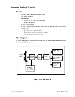
Analog Inputs
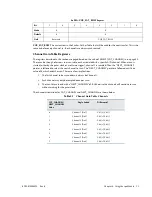
The input multiplexer in aAIO accepts eight single ended analog inputs. Any combination of ranges can be used
for these inputs. Pairs of analog inputs can be combined to form up to four differential inputs.
Channel-Gain Table
A Channel-Gain table is provided to control the mode and range of each channel and the order that they are
sampled in. Each row in the scan table is associated with a specific A/D channel. When a scan is started (either
by the pacer clock or a software trigger), channel 1 is sampled. Then the “NEXT_CHANNEL” pointer is followed
to select the next channel to scan. The “NEXT_CHANNEL” pointer is followed until it is a value of 0, which ends
the scan. There are a few implications:
1.
The first channel to be scanned must always be Channel 1.
2.
Each channel may only be sampled once per scan.
3.
The scan list must end with a “NEXT_CHANNEL” of 0. Otherwise the channels will continue to scan
without waiting for the pacer clock.
The Channel-Gain Table contains all of the channel-specific settings and status. This includes the mode
(single-ended or differential), and range. It also contains the filter and threshold setting as well as the interrupt
status and enable bits. The A/D Result register, which returns the last conversion for this channel, is also within
the Channel-Gain Table.
Analog to Digital Converter
The Analog to Digital Converter used in aAIO is a 16-bit, 100 ksps converter. There is no calibration required, and
is typically accurate to within 10mV.
Programmable Digital Filter
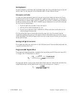
The programmable digital filter provides a single pole Infinite Impulse Response (IIR) filter on each channel. This
is a unity-gain filter. The filtered data has a value of:
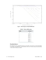
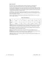
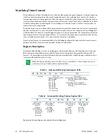
The response of the filter is shown in Figure 2 below. Table 1 below shows the -3 dB cutoff for each of the filter
settings. Both the Figure and the Table are relative to the per-channel sample rate (f
s
), which is:
D
n
D
n
1
–
2
ORDER
1
–
(
)
×
[
]
NewSample
+
2
ORDER
----------------------------------------------------------------------------------------------
=
f
s
40MHz
PACERDIVIDER
1
+
(
)
--------------------------------------------------------
=
Summary of Contents for BDM-610000075
Page 3: ... Accessing the Analog World www rtd com ISO9001 and AS9100 Certified CMX32M cpuModules ...
Page 4: ...iv CMX32M cpuModule BDM 610000075 Rev B ...
Page 30: ...22 CMX32M cpuModule BDM 610000075 Rev B ...
Page 60: ...52 CMX32M cpuModule BDM 610000075 Rev B ...
Page 102: ...94 CMX32M cpuModule BDM 610000075 Rev B ...
Page 116: ...108 CMX32M cpuModule BDM 610000075 Rev B ...

