background image


M0416-1 version 3.2 

2 INSTALLATION 

2.1 Installation of tool changer on robot 


Action 

Note 

Safety


Read the safety 

section 1.2

Service position


Place the robot in service position. 

Power off


Switch the power off and lock the 
circuit breaker. 

NOTE!

 Read the safety chapter for the 

robot. 

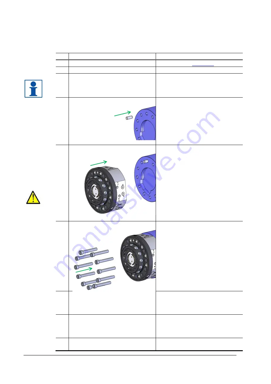
Mount guide pin 


Press the enclosed guide pin into the 
robot flange. 

Alternatively, if adaptation plate is 
used

Mount the adaptation plate on the robot 
flange (see tightening torques above). 
Press the enclosed guide pin into the 
adaptation plate. 

Fit tool changer 


Lift the tool changer to the robot flange 
(or adaptation plate). The arrow on the 
front of the tool changer indicates the 
position of the hole for the guide pin. 
Make sure that the guide pin is fitted to 
the guide hole in the tool changer. 
 

WARNING!

 The tool changer may 

cause personal injury and equipment 
damage if dropped. 
 

Mount tool changer 


Mount the tool changer with the 
enclosed screws. Use an Allen key for 
tightening (see tightening torques 
above). 


Connect air hoses 
 

Connect the air hoses according to 
markings. Pneumatic diagrams are 
found in the Product Description of 
respective unit. 

Connect electrical signals 

(electrical 

versions only)


Connect electrical connectors in 
accordance with selected unit. Circuit 
diagrams are found in the Product 
Description of respective unit. 

Power on


Unlock the circuit breaker and switch 
the power on. 

Summary of Contents for Compact Series

Page 1: ...Installation and Maintenance Manual Tool changers TC100 TC1000 M0416 1 Tool changers Swivels Swivels Tool changers Grippers Hose packages Valve Units Tool systems ...

Page 2: ...2 M0416 1 version 3 2 ...

Page 3: ...use of this document or the software or hardware described in this document The document or parts of it may not be reproduced or copied without prior permission from Robot System Products AB It may neither be imparted to a third party nor otherwise be used without authorization Infringement hereof will be subject to action in accordance with the applicable laws Further copies of this document can ...

Page 4: ... 1 2 Every six months or 250 000 tool changes 11 3 1 3 To replace when damaged or worn out 11 3 2 Specification of maintenance activities 12 3 2 1 Visual inspection of tool changer 12 3 2 2 Visual inspection and cleaning of tool attachment 13 3 2 3 Cleaning and lubrication of tool changer 13 3 2 4 Cleaning and lubrication of tool attachment 15 4 DISMOUNTING AND REPLACEMENT 16 4 1 Replacement of to...

Page 5: ...fully maintained Our Swivel tool changers unite the TrueConnect mechanism with our swivel technology combining the best out of the two technologies With RSPs unique Circular Rotators cables and hoses can be freely selected with high robot flexibility maintained and the space requirements reduced Our integrated Tool systems are delivered as complete plug and play solutions designed for quick and si...

Page 6: ... tool changer if the air pressure is safely switched off WARNING Be aware that tool changer and tool attachment may cause personal injury and equipment damage if dropped NOTE The tool changer shall always be in locked position also when empty to avoid unexpected locking if air pressure is lost WARNING Electric signals must be disconnected switched off when docking the tool attachment This is to pr...

Page 7: ...ing Pair of pliers For dismounting the signal pins Screwdriver For removing the air sealings 1 5 Required products Product Specification Note Grease 3HXG1000 413 Magnalube G Teflon grease Air sealings Grease I0876 Molykote BR2Plus For locking balls Cleaning agent Industrial alcohol or similar For cleaning of tool changer and tool attachment Glue Loctite 480 or similar For gluing the air sealings C...

Page 8: ... adaptation plate The arrow on the front of the tool changer indicates the position of the hole for the guide pin Make sure that the guide pin is fitted to the guide hole in the tool changer WARNING The tool changer may cause personal injury and equipment damage if dropped 6 Mount tool changer Mount the tool changer with the enclosed screws Use an Allen key for tightening see tightening torques ab...

Page 9: ...stening screws can be entered either from the tool attachment side or the tool side Screws are specified in the Product Description of respective tool attachment Mount the tool attachment using a torque wrench See tightening torques above NOTE For TA100 fastening screws can only be entered from the tool attachment side 5 Connect air hoses Connect air hoses to the tool attachment Pneumatic diagrams...

Page 10: ... position is found when the tool attachments are parallel centered and the engraved arrows are on the same line 4 Save the position The robot can move to this position with high speed 5 Dismount the spare tool attachment 6 Go back to the saved position and move the tool changer in axis 6 direction the remaining distance to the tool attachment mounted at the tool 7 Save the position The robot shoul...

Page 11: ... Visual inspection section 3 2 1 Locking balls Check locking balls section 3 2 1 Air sealings Check air sealings section 3 2 1 Spring loaded pins Check spring loaded signal section 3 2 1 Tool attachment General Visual inspection of tool attachment and cables section 3 2 2 Cleaning Tool attachment Signal contacts Clean contact surfaces section 3 2 2 3 1 2 Every six months or 250 000 tool changes Th...

Page 12: ...position Check air sealings Check that the air sealings are clean For cleaning see section 3 2 3 Check that the air sealings are not damaged For making replacements see section 4 3 1 Check spring loaded signal pins electrical versions only Check that the spring loaded signal pins are clean For cleaning see section 3 2 3 Check that the spring loaded signal pins are not worn out or damaged For makin...

Page 13: ...es and squeezing replace if damaged Check tool attachment in general Check the tool attachment for damages For replacement see section 4 2 3 2 3 Cleaning and lubrication of tool changer The following maintenance activities should be carried out on the TC every 6th month or after 250 000 tool changes whichever comes first Action Note Clean locking balls Check the locking balls and wipe them clean w...

Page 14: ...rtant that this is done or else there is a risk that the tool attachment jams Clean air sealings Wipe air sealings clean with a lint free cloth Clean spring loaded signal pins electrical versions only Clean the contact surfaces of the spring loaded signal pins with a nylon brush NOTE Signal pins shall be cleaned whenever blackened ...

Page 15: ...h or after 250 000 tool changes whichever comes first Action Note Clean locking cavities Clean the cavities of the locking balls with a lint free cloth NOTE It is important that this is done or else there is a risk that the tool attachment jams Clean contact surfaces of air sealings Wipe the contact surfaces of the air sealings clean with a lint free cloth ...

Page 16: ...Dismount hoses Dismount the air hoses from the tool changer NOTE Make sure that no dirt enters the air hoses 7 Release electrical connectors NOTE Handle the contact with care as it is sensitive to mechanical damage Make sure that no dirt enters the contacts 8 Remove screws Remove the screws holding the tool changer to the robot flange WARNING The tool changer is heavy and may cause personal injury...

Page 17: ...Make sure that no dirt enters the contacts 4 Dismount hoses Dismount the air hoses from the tool attachment NOTE Make sure that no dirt enters the air hoses 5 Remove screws Remove the screws holding the tool attachment to the tool WARNING The tool attachment is heavy and may cause personal injury and equipment damage if dropped 6 Dismount tool attachment NOTE A guide pin is mounted between the too...

Page 18: ...ling holes Remove all remaining parts of the sealing 3 Mount new air sealings Tap in the air sealings with a plastic mallet 4 3 2 Replacement of O ring Action Note 1 Remove O ring Remove the O ring on the ball holder at the tool changer 2 Clean surface Clean the surface at the O ring location 3 Add grease Add a small amount of grease Magnalube G on the new O ring 4 Mount new O ring ...

Page 19: ...f and lock the circuit breaker 2 Remove signal pins Pull out the signal pins with a pair of pliers 3 Replace signal pins Fit the new signal pins by pushing them into the sleeves NOTE The signal pins should be fully pressed into the sleeve using a small screwdriver 4 Power on Unlock the circuit breaker and switch the power on ...

Page 20: ... and used in new products They shall be sorted according to type and surface coating and handed over to an authorized recycling facility Metal components of steel and aluminium are substantial in size and easy to identify Copper is primarily used in transmission of power for spot welding Silver or gold plating of contact surfaces may occur Plastics Thermoplastics can in general be re heated and re...

Page 21: ...M0416 1 version 3 2 21 ...

Page 22: ...22 M0416 1 version 3 2 ...

Reviews: