Section 6 Maintenance
S7M / S8M Manual
www.rottlermfg.com
6-20
Inner Spindle Adjustment
Turn off all power to the machine before continuing.
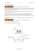
Remove the two screws holding the small nameplate (502-1-19C) to the front of the upper housing. Inside
the exposed opening is the spindle adjustment nut (7020). The spindle adjustment nut has holes drilled
around its perimeter to accept an adjustment rod.
Insert an adjustment rod into the spindle adjustment nut. The adjustment rod should be 1/4 - 5/16 inch
diameter and 8 to 10 inches long.
Carefully rotate the cutterhead counter-clockwise, (looking from above the cutterhead) letting the
adjustment rod move against the end of the slot. This tightens the inner spindle adjustment. The
cutterhead will be easy to turn and you should be able to feel the spring loaded detent in the adjustment
nut.
At some point the torque required to turn the cutterhead will sharply increase, immediately stop turning
the cutterhead.
Do not over tighten or severe bearing damage will occur.
Turn the cutterhead clockwise one or two detents.
Remove the adjustment rod and replace the nameplate
Summary of Contents for S7M
Page 2: ......
Page 4: ......
Page 8: ...Section 1 Introduction S7M S8M Manual www rottlermfg com 1 4 ...
Page 17: ...Section 2 Installation S7M S8M Manual www rottlermfg com 2 8 ...
Page 18: ...Section 2 Installation S7M S8M Manual www rottlermfg com 2 9 ...
Page 38: ...Section 5 Operating Instructions S7M S8M Manual www rottlermfg com 5 9 ...
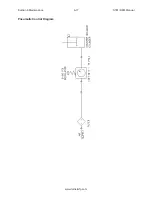
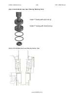
Page 57: ...Section 6 Maintenance S7M S8M Manual www rottlermfg com 6 17 Pneumatic Control Diagram ...
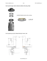
Page 66: ...Section 6 Maintenance S7M S8M Manual www rottlermfg com 6 26 ...
Page 68: ...Section 7 Troubleshooting S7M S8M Manual www rottlermfg com 7 2 ...
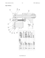
Page 71: ...Section 8 Machine Parts S7M S8M Manual www rottlermfg com 8 2 Pneumatic Assembly ...
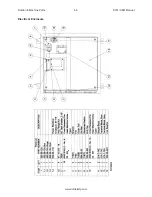
Page 72: ...Section 8 Machine Parts S7M S8M Manual www rottlermfg com 8 3 Electrical Enclosure ...
Page 74: ...Section 8 Machine Parts S7M S8M Manual www rottlermfg com 8 5 Upper Housing ...
Page 76: ...Section 8 Machine Parts S7M S8M Manual www rottlermfg com 8 7 Spindle Base Front Section ...
Page 77: ...Section 8 Machine Parts S7M S8M Manual www rottlermfg com 8 8 Inner Outer Spindle Assembly ...
Page 78: ...Section 8 Machine Parts S7M S8M Manual www rottlermfg com 8 9 Spindle Base Bushings ...
Page 79: ...Section 8 Machine Parts S7M S8M Manual www rottlermfg com 8 10 Spindle Base Assembly ...
Page 80: ...Section 8 Machine Parts S7M S8M Manual www rottlermfg com 8 11 Left Ballscrew Support ...
Page 81: ...Section 8 Machine Parts S7M S8M Manual www rottlermfg com 8 12 Right Ballscrew Support ...
Page 82: ...Section 8 Machine Parts S7M S8M Manual www rottlermfg com 8 13 Home and Limit Switches ...
Page 83: ...Section 8 Machine Parts S7M S8M Manual www rottlermfg com 8 14 Pendant Assembly ...
Page 84: ...Section 8 Machine Parts S7M S8M Manual www rottlermfg com 8 15 Spindle Base ...
Page 85: ...Section 8 Machine Parts S7M S8M Manual www rottlermfg com 8 16 Chip Shield 14 16 ...
Page 86: ...Section 8 Machine Parts S7M S8M Manual www rottlermfg com 8 17 14 Fly Cutter ...
Page 87: ...Section 8 Machine Parts S7M S8M Manual www rottlermfg com 8 18 Chip Chute ...
Page 89: ...Section 8 Machine Parts S7M S8M Manual www rottlermfg com 8 20 Riser Set ...
Page 90: ...Section 8 Machine Parts S7M S8M Manual www rottlermfg com 8 21 Air Diagram ...
Page 92: ...Section 9 Options S7M S8M Manual www rottlermfg com 9 2 ...
Page 94: ...Section 10 Material Data Safety Sheets S7M S8M Manual www rottlermfg com 10 2 ...
Page 95: ...Section 10 Material Data Safety Sheets S7M S8M Manual www rottlermfg com 10 3 ...
Page 96: ...Section 10 Material Data Safety Sheets S7M S8M Manual www rottlermfg com 10 4 ...


