© Rototilt Group AB
2018-08-31
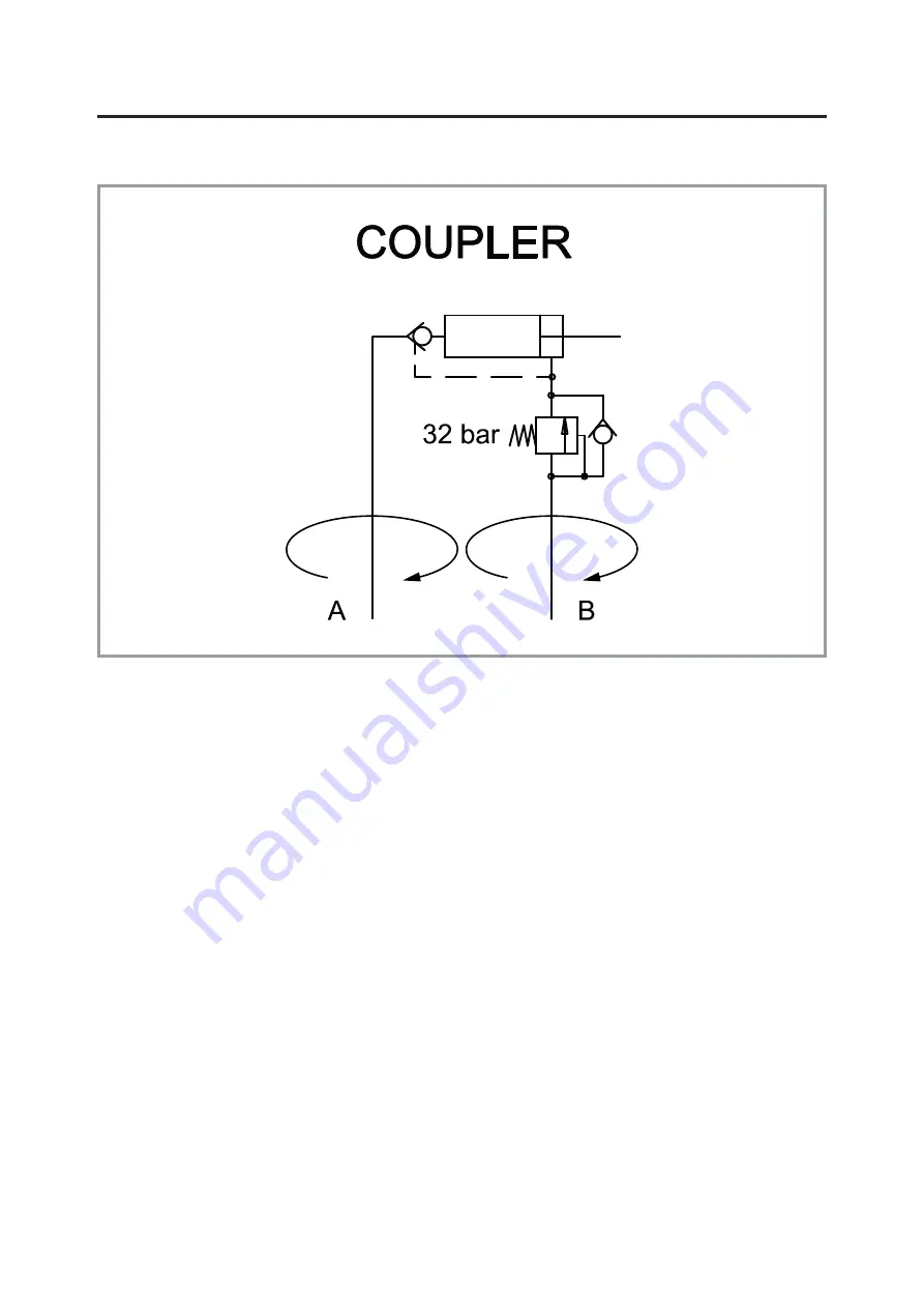
Hydraulic diagram Coupler
English
EN
2200006_ _7434
Page 1: ...3 Lamp with holder 4 Hydraulic hose and adapter Single locking wedge 5 Indicator rod 6 Locking wedge 7 Lock cylinder with sensor 8 Pin and bearing Twin locking cylinders 9 Indicator holders 2 pcs 10 I...
Page 2: ...is a risk that the load or part of the load will fall nobody may be present beneath a hoisted object WARNING From a safety point of view the quick coupler with its locking function is a very importan...
Page 3: ...tructions for use for each control system Indicator rod The quick coupler has an indicator rod that shows if the lock function is closed or open See figure above left The indicator rod must be visible...
Page 4: ...is not working properly Contact your dealer maintenance service provider immediately if you detect faults Operation IMPORTANT If the attachment can fall or change position in connection with the proc...
Page 5: ...the operator s position rotate the quick coupler and check that the lock wedge lock pistons have engaged lock position If you are still unsure exit the cab and perform a visual inspection After a too...
Page 6: ...tool is subjected to external damage it must be removed from operation until inspection and any necessary action is taken WARNING Take care of the environment Use a drip pan to avoid harming the envir...
Page 7: ...Hydrema Max weight base machine 2 tons 3 5 tons 6 tons 6 5 tons 11 tons 12 tons Rototilt model R4 R5 R6 R8 R9 Quick coupler S45 S50 S60 MH18 S60 MH18 S70 S70 S80 S80 Max weight base machine 12 tons 1...
Page 8: ...Rototilt Group AB 2018 08 31 Hydraulic diagram Coupler English EN 2200006_ _7434...