Keeping the World Flowing
17
12.0 Operation
12.6 Hydraulic Manual Override
Single-Acting Actuator
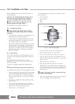
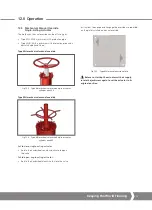
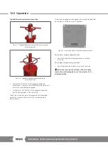
Type HPA hydraulic manual override
The unit consists of two main components:
• the hydraulic cylinder
• the pump/tank assembly
The hand pump (1) supplies high-pressure fluid to the
hydraulic cylinder (2) that will stroke the actuator and
compress the spring.
1
5
4
3
2
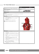
Fig 12.11 Type HPA manual override
Installation
The oil tank must be installed in a vertical position with
respect to the floor. The fill port/breather (4) must be turned
upward to avoid any oil discharge from the fill port/breather
of the tank.
NOTE:
Before starting-up the actuator with a hydraulic
override, check if the plug (4) has been replaced with a
breather to prevent oil discharge from the tank during
shipment.
If not, replace the plug with the breather.
Proper oil level is approximately 25 mm (1") below the fill/
breather port.
Oil level should be checked with the tank in a vertical position
and with the actuator in fail position (spring decompressed).
Filling procedure
If the actuator is shipped without oil in the HPA, please refer
to filling procedure described in PM-LP-005.
Operation with Hydraulic Pump
• The manual valve (4) must be in the open position
• Close the on/off selector valve (5) by turning in fully
clockwise
• Operate the pump (1) via the handle (3) will stroke the
actuator and compress the spring
• When the actuator has reached the desired position of
travel, it can be locked in position by closing the manual
valve (4)
• To allow the spring to decompress, the manual valve
(4) must be moved to the open position and the on/off
selector valve (5) backed out by turning anti-clockwise
After each use, verify that the manual override has
been disengaged.
A4
US
US
A4
US
A4
A4
US
Summary of Contents for LP/S Series
Page 89: ...Keeping the World Flowing 89...

